
Content last revised on October 28, 2026
Benchtop Waveform Tuning: Mitigating Stress via Regenerative DC-Bus Voltage Surge Dissipation on 6MBP30RTB060-12
Capture the DC-link voltage during a controlled deceleration and compare its rise with the braking command before changing the power module. For the Fuji Electric 6MBP30RTB060-12, a regenerative voltage excursion, excessive switching overshoot, and an overloaded thermal interface require different corrective actions; a shared drive alarm does not establish which condition occurred.
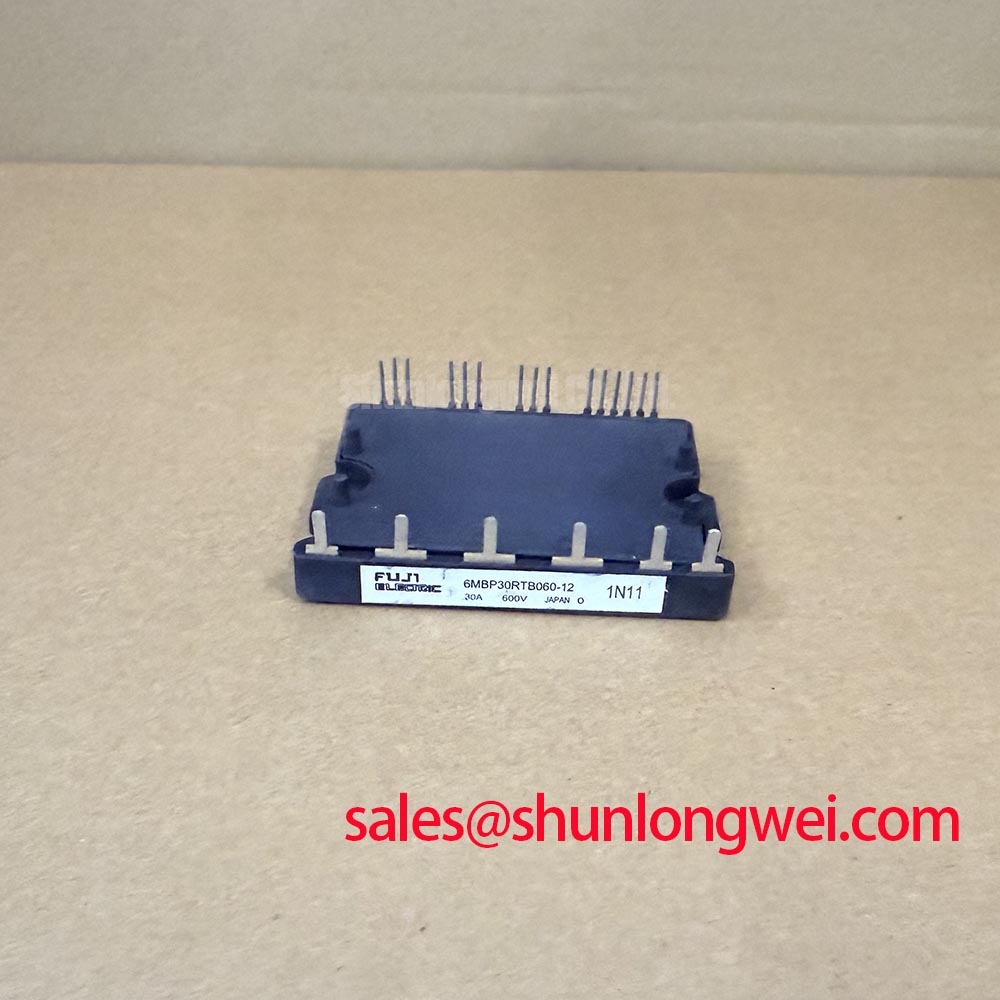
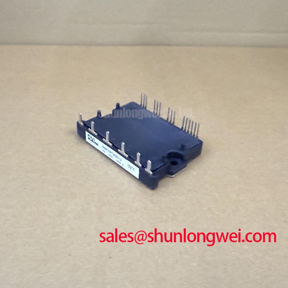
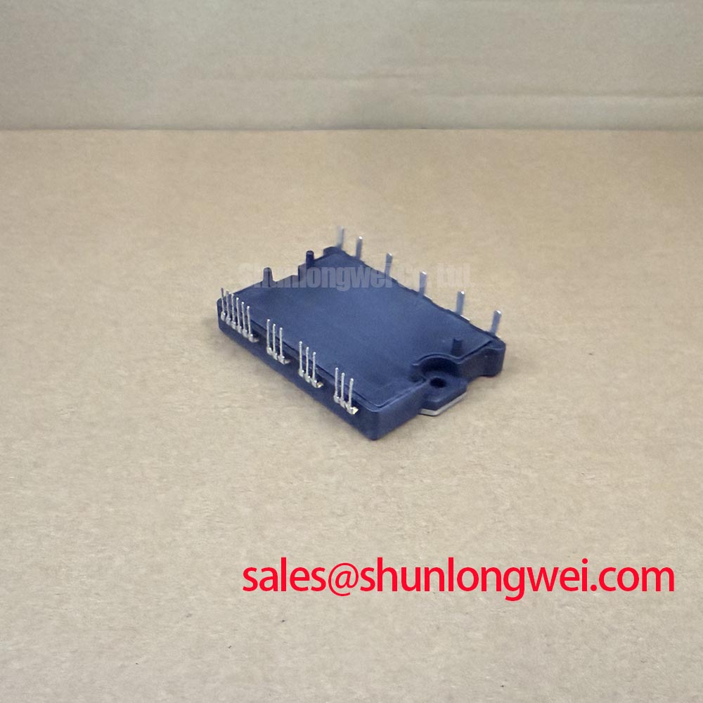
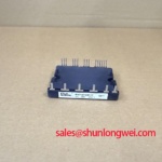
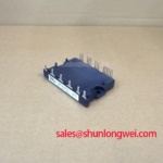
The 6MBP30RTB060-12 is an IPM module with a 600 V voltage rating and a 30 A current rating. These ratings establish the starting point for electrical assessment. Replacement evaluation also requires the matching terminal arrangement, control interface, mounting drawing, and rating conditions. As a Design Consideration, compatibility with a precision stepper or BLDC motor servo motion actuator should be assessed against the existing power-stage schematic and control requirements.
Record the bus-voltage trajectory alongside braking activation and phase current to establish whether regenerated energy is reaching an effective dissipation path. As a Design Consideration, a rising bus during deceleration can reflect the commanded stopping profile, unavailable energy absorption, or a braking circuit that activates incorrectly. Compare the timing of these signals before attributing the event to the IPM.
Trace the braking branch on the equipment schematic and identify its switching device, resistor connections, command source, and thermal protection. Treat this branch as a system circuit: the IPM designation alone does not establish an internal braking transistor. Where a separate braking switch is fitted, assess its voltage capability, pulse-current limits, switching behavior, and thermal loading against the actual braking event. Evaluate resistor pulse-energy capability and repetitive heating separately, since surviving an isolated stop does not establish suitability for repeated operation.
For Engineering Calculation, the energy assessment should account for the reduction in stored mechanical energy during deceleration, the energy accepted by the DC-link capacitors, and losses elsewhere in the drive. Motor speed, reflected load inertia, stopping time, and repetition determine the resulting dissipation requirement. Use the equipment’s measured operating cycle to establish these inputs; selecting a resistor from motor nameplate power alone can overlook the braking pulse that governs its suitability.
Examine the braking waveform at the switch as well as across the DC link. A sustained bus rise and a narrow switching spike point toward different parts of the energy path. As an Engineering Recommendation, use suitably rated differential measurement equipment and a probe arrangement with adequate common-mode performance, then compare captures taken under repeatable conditions. Probe placement matters because a long measurement loop can add ringing that resembles a circuit problem.
Keep the high-current commutation path compact and arrange the outgoing and return conductors close together where the approved mechanical design permits. Required spacing around live conductors should follow the equipment’s insulation coordination, working voltage, installation conditions, and applicable requirements. Resistor placement also needs a thermal assessment so that braking heat does not raise the cooling-air temperature entering the module heatsink.
💡 Pro Tip: Keep the DC-link feed and return geometry balanced to reduce commutation-loop inductance, then verify turn-off voltage margin with a controlled double-pulse test using the intended bus arrangement.
During sourcing comparisons, the 6MBP150TEA060 can serve as a separate Fuji module reference for reviewing electrical and mechanical differences. Its relationship to the same manufacturer does not establish interchangeability. Compare terminal functions, control-supply requirements, protection behavior, outline dimensions, and cooling interfaces before considering any substitution for the 6MBP30RTB060-12.
Field Diagnostics & Commissioning: Junction-to-Case Thermal Network Simulation in 6MBP30RTB060-12 Topologies
Build the transient thermal assessment from the actual current pulse and switching-loss profile, rather than applying the continuous current rating to every overload event. As a Design Consideration, junction temperature responds faster than the heatsink surface, so a moderate external temperature during a brief overload can conceal a larger junction excursion. Capture the load duration, repetition, starting temperature, and cooling condition together.
A multi-RC thermal model needs device-specific transient thermal impedance data or manufacturer-provided coefficients. Preserve the distinction between a fitted junction-to-case response and a physical network intended to connect to additional thermal layers: an arbitrary connection between models can produce misleading temperature predictions. For the 6MBP30RTB060-12, thermal coefficients, junction-temperature limits, and loss curves belong in the matching datasheet review rather than being borrowed from a neighboring part number.
As an Engineering Calculation method, apply the time-dependent semiconductor losses to the appropriate transient thermal response, then combine the resulting junction-to-case rise with the corresponding case temperature. Repeated pulses require the residual temperature from preceding events to remain in the calculation. Where transistor and diode losses differ, evaluate their relevant thermal paths instead of assigning the same loss distribution to every switching position. This produces a useful peak-temperature assessment without treating average dissipation as a complete description of overload stress.
Evaluate switching-frequency changes through their effect on losses and cooling demand. As a Design Consideration, increasing switching frequency can increase switching dissipation, while changes in current ripple and modulation can alter the conduction-loss distribution. Use operating points supported by the module documentation and controller configuration. A frequency sweep should therefore record electrical conditions and temperature together, with sufficient stabilization to distinguish heatsink warming from the faster response to load pulses.
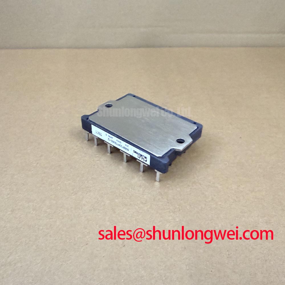
Inspect the heatsink contact surface and mounting arrangement when measured case temperatures depart from the thermal model. An Engineering Recommendation is to check surface cleanliness, flatness, interface coverage, and the specified tightening sequence before changing airflow hardware. Thermal interface material should fill surface irregularities without preventing the intended seating of the module. Obtain coating requirements, fastener details, and mounting torque from the applicable assembly instructions; a generic grease thickness or bolt torque is not an official specification for this package.
Use the module’s documented mounting arrangement when evaluating clamping force. Pressure-contact practices, calibrated disc-spring loading, and double-sided cooling should not be transferred to this package without explicit mechanical support. Uneven fastening can affect interface contact, while an incompatible fixture can introduce mechanical loading outside the intended installation. Assess the assembled interface through inspection and repeatable thermal measurements rather than assuming that greater tightening force improves heat transfer.
At elevated ambient temperature, assess airflow where it actually enters the heatsink and inspect restrictions, contamination, and recirculation within the enclosure. As a Design Consideration, fan operation alone does not establish adequate cooling. The thermal model should use boundary conditions representative of the installed equipment. For broader discussion of converter losses and thermal utilization, Peak Efficiency in Solar and Energy Storage provides system-level context; it does not establish a service-life rating for this module.
6MBP30RTB060-12 Circuit Protection & Reliability: Calibrating Long Motor Lead Reflected Wave Voltage
Measure the switching waveform at both the inverter output and the motor terminals when cable-related voltage stress is suspected. As a Design Consideration, cable propagation and impedance mismatch can produce reflected voltage at the motor even when the inverter-terminal waveform appears acceptable. Compare measurements using consistent probe bandwidth and connection geometry, because inconsistent setups can obscure the difference between terminal reflection and local switching ringing.
The reflection amplitude depends on the cable, motor impedance, pulse rise time, and interaction between successive transitions. Assess the measured peak and ringing duration against the connected equipment’s documented limits rather than assigning a universal multiplication factor. The module’s 600 V rating is relevant to its semiconductor voltage boundary; motor-terminal insulation stress is a separate assessment involving the motor, cable, and output waveform.
When evaluating an output choke or a voltage-slew-rate filter, use the installed cable characteristics, load current, switching conditions, and motor insulation requirements as selection inputs. As an Engineering Recommendation, check filter voltage drop, heating, resonance, and the effect on current regulation across the intended operating range. Filter sizing belongs to the complete output network, and an existing filter should be inspected for correct connection and condition before a different component is selected.
Separate cable reflection from control-related switching disturbance by correlating the output waveform with the relevant control signals and fault indication. Miller coupling and parasitic inductance are Design Considerations at the driver and switching-device interface. For an IPM-based assembly, review the documented control connections and return paths; changes to internal gate damping or negative gate bias cannot be assumed available. The manufacturer’s Fuji Electric Power Semiconductor & IPM Modules resource provides the appropriate manufacturer context for locating IPM technical guidance.
Review fault handling against the module’s documented protection functions and the equipment schematic. Desaturation detection, soft shutdown, and short-circuit withstand capability are specific characteristics that require explicit manufacturer support before being attributed to this model. As a Design Consideration, the controller should respond correctly to the module’s actual fault behavior, including inhibition, reset conditions, and restart sequencing. Validate those interfaces with controlled commissioning tests rather than an intentional uncontrolled output short circuit.
Close the cable-stress investigation by repeating the waveform capture with the intended cable routing, output network, and representative load conditions. Record the motor-terminal peak, inverter-terminal peak, bus behavior, and fault timing together. If the intervention changes ringing but raises filter temperature or disrupts current regulation, reassess the complete network before accepting the change; the useful result is a reproducible electrical improvement within the connected components’ documented limits.