Content last revised on September 21, 2026
Benchtop Waveform Tuning: Mitigating Stress via Transient Thermal Impedance on 6MBP75RJ120
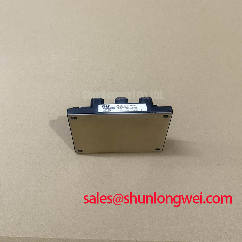
With the converter isolated, begin by confirming that the nameplate identifies 6MBP75RJ120, then inspect the module case, terminals, mounting face, and surrounding busbar hardware for heat discoloration, looseness, moisture traces, or conductive debris. This Fuji Electric power module is officially rated at 1200 V and 75 A, with the official package description listed as Module. These ratings establish the electrical identity to verify before a repair team reconnects a drive or replaces a failed assembly.
| Parameter | Official Specification |
|---|---|
| Manufacturer | Fuji Electric |
| Part number | 6MBP75RJ120 |
| Voltage rating | 1200 V |
| Current rating | 75 A |
| Package | Module |
Before applying full power after module replacement, capture collector-emitter voltage, gate command, load current, and heatsink temperature under controlled operating conditions. Pulsed current can produce junction temperature movement that is not apparent from a heatsink reading alone. A transient thermal impedance network is therefore useful when the applicable Fuji Electric documentation supplies the required thermal data and test conditions. It lets the system engineer relate pulse width, repetition pattern, dissipation, and case temperature to an estimated junction temperature margin.
This is an Engineering Calculation, not an official operating guarantee for the installed machine. The calculation must use the switching losses, conduction losses, thermal interface condition, and cooling performance measured or documented for that particular converter. If waveform ringing, rising case temperature, or intermittent protection trips appear after servicing, compare the behavior with a known healthy power stage before changing gate components or protection thresholds.
For industrial inverter welders and medium frequency induction heating power supplies, airflow paths deserve the same attention as electrical connections. Dust accumulation can reduce heat transfer, while aged thermal interface material can create uneven contact across the module baseplate. ⚠️ Maintenance Note: Periodically monitor terminal and heatsink contact temperature rise, then verify that cooling passages remain clean and unobstructed.
6MBP75RJ120 Circuit Protection and Reliability: Calibrating Symmetrical Busbar Geometry for High Current Operation
The 75 A current rating is an official module specification, but actual current distribution in a converter also depends on the complete power path. Where parallel current paths are present, equal conductor length, comparable contact resistance, matched gate drive routing, and similar thermal conditions are Design Considerations for stable sharing. The positive temperature behavior of IGBT saturation voltage can assist static current balance in suitable operating regions, but it does not correct unequal dynamic gate loops or unequal busbar inductance.
During service work, inspect terminal hardware, busbar flatness, and evidence of fretting at bolted interfaces. A voltage difference observed between parallel paths may indicate an imbalance, but the cause should be verified through controlled measurements rather than assigned to one component. Gate command timing and collector-emitter waveforms should be reviewed together because a nominally identical drive signal can arrive differently at the module through unequal wiring.
High-speed semiconductor fuse coordination is also a system-level Design Consideration. Fuse clearing energy, fault current rise, upstream source impedance, and the module’s applicable surge and short-circuit limits must be checked against the manufacturer documentation for the full assembly. Protection settings should be validated on the actual power stage, particularly after any busbar, driver board, or cooling-system change.
For a separate Fuji Electric module with different published ratings and mechanical integration requirements, engineers can compare the 6MBI100S-140 against the original equipment electrical diagram, terminal arrangement, cooling interface, and gate drive documentation. A part number comparison alone cannot establish interchangeability.
6MBP75RJ120 Thermal Electrical Optimization: Turn Off di/dt Induced Peak Voltage Clamping and Practical Tuning
At turn-off, peak collector-emitter voltage is governed by the DC bus voltage plus the inductive contribution created by commutation-loop inductance and current fall rate. In engineering terms, the inductive component follows the relationship between loop inductance multiplied by di/dt. This is an Engineering Calculation principle; the measured peak is determined by the installed busbar geometry, driver behavior, snubber network, load, probe method, and operating point.
Minimize parasitic loop inductance through compact, symmetrical power paths when suppressing turn-off overshoot, then verify peak margins against the DC-link voltage during switching tests. A snubber cannot be selected responsibly from the module voltage rating alone. Its function, capacitance, damping path, dissipation, and physical placement must be determined from measured ringing frequency and energy in the actual converter.
Desaturation protection and controlled soft turn-off are likewise system functions rather than official built-in characteristics stated by the basic module identification. The driver should be assessed for its response to a detected overcurrent event, including whether the gate discharge behavior and blanking method remain appropriate across normal process variation. Guidance on the interaction among gate drive, layout, cooling, and power topology is available in this IGBT Design & Integration reference.
Fuji Electric’s power semiconductor and IPM module information provides useful manufacturer context when matching product documentation to a repair record. The system integrator should verify the required driver supply, gate polarity, terminal assignment, and protection sequence from the original equipment documentation.
Benchtop Waveform Tuning: Mitigating Stress When Assessing High Altitude Failure Risks on 6MBP75RJ120
No failures-in-time value, single-event burnout rate, altitude derating curve, or service-life figure is stated by the supplied official parameters for 6MBP75RJ120. It would therefore be inappropriate to assign a numerical reliability rate or a fixed high-altitude operating limit to this module. Such conclusions require applicable manufacturer data, validated system conditions, and a defined environmental standard.
For equipment operated at elevated installation sites, treat altitude as a Design Consideration covering enclosure cooling, reduced air density, clearance and creepage requirements, contamination control, and DC bus operating stress. The maintenance team should record ambient conditions, cooling performance, process duty cycle, and measured switching waveforms at the site. Those records help distinguish a thermal limitation, an insulation concern, a bus transient issue, or an external control fault without assuming one cause.
Where high-energy faults are a concern, review the converter’s protective sequence from detection through gate removal and source isolation. Test results should confirm that the driver isolation barrier, current sensing path, protection logic, fuse coordination, and mechanical connections work together under controlled conditions. This approach supports evidence-based maintenance without presenting unverified lifetime or environmental reliability claims as module specifications.