


Content last revised on March 28, 2026
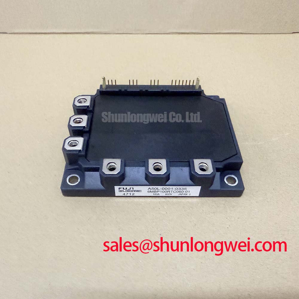
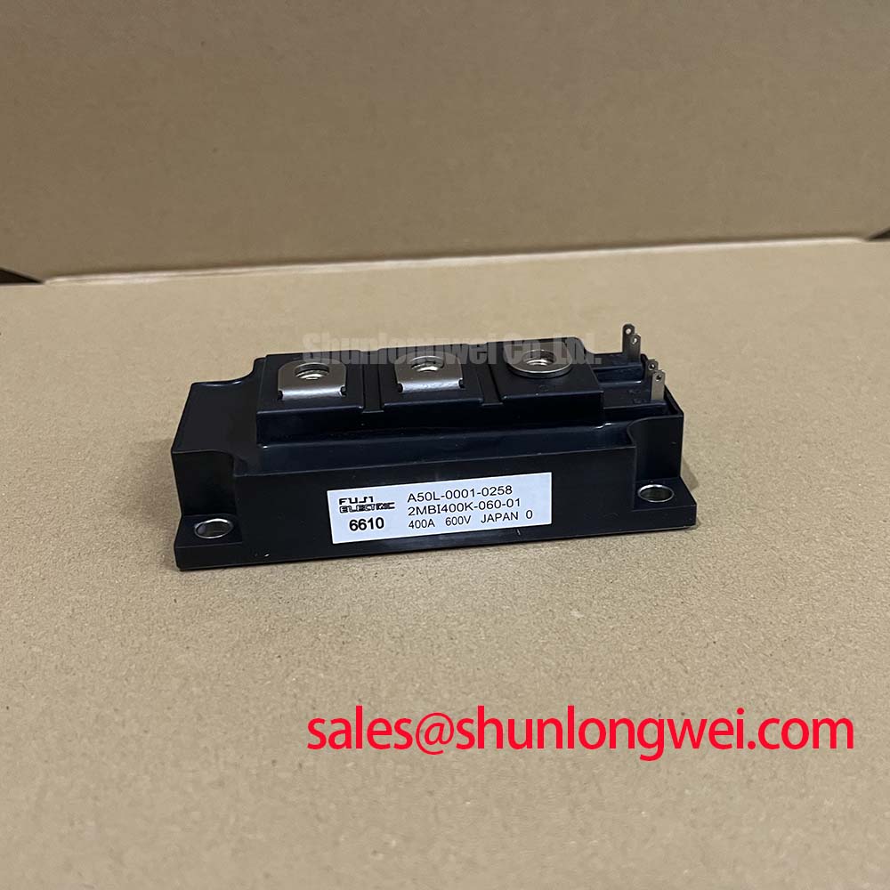
Fuji 2MBI400K-060-01: A 600V/400A Dual IGBT Module Review
Optimized for High-Frequency Power Conversion and Efficiency
The Fuji Electric 2MBI400K-060-01 IGBT Module is engineered to excel in high-frequency power systems by fundamentally minimizing energy losses. Delivering robust performance with specifications of 600V | 400A | Rth(j-c) 0.085°C/W (max), this dual IGBT module provides a platform for superior power density. Its key benefits include markedly reduced thermal load and the facilitation of more compact system designs. The module's low-inductance internal layout is a crucial design element, enabling faster, cleaner switching by mitigating the voltage overshoots that often limit performance in demanding, high-speed applications.
Key Parameters Engineered for Switching Performance
The technical specifications of the 2MBI400K-060-01 are carefully balanced to deliver high-speed operation while maintaining control over thermal performance. For engineers and system designers, these numbers provide the data needed for accurate modeling and reliable system implementation. The parameters listed below are derived directly from the manufacturer's documentation for the 2MBI400K-060 base model.
| Parameter | Symbol | Test Conditions | Value | Unit |
|---|---|---|---|---|
| Absolute Maximum Ratings | ||||
| Collector-Emitter Voltage | VCES | - | 600 | V |
| Gate-Emitter Voltage | VGES | - | ±20 | V |
| Continuous Collector Current | IC | TC = 80°C | 400 | A |
| Peak Collector Current | ICP | 1ms pulse | 800 | A |
| IGBT Characteristics | ||||
| Collector-Emitter Saturation Voltage | VCE(sat) | IC = 400A, VGE = 15V | 2.7 (Max) | V |
| Turn-on Time | ton | VCC = 300V, IC = 400A, VGE = ±15V | 0.3 (Typ) | µs |
| Turn-off Time | toff | 0.5 (Typ) | ||
| Thermal Characteristics | ||||
| Thermal Resistance (IGBT) | Rth(j-c) | Junction to Case | 0.085 (Max) | °C/W |
| Thermal Resistance (FWD) | Rth(j-c) | Junction to Case | 0.15 (Max) | °C/W |
Application Arenas: Where Speed and Efficiency Converge
The specific performance profile of the Fuji Electric 2MBI400K-060-01 makes it a strong candidate for power conversion systems where operational frequency and efficiency are primary design drivers. Its architecture provides tangible benefits in several key industrial domains.
- High-Frequency Power Supplies: In applications like industrial welding and induction heating, the module's fast switching capabilities (ton/toff of 0.3/0.5µs) allow for higher operating frequencies. This directly enables the use of smaller, lighter magnetic components, contributing to a higher overall power density and reduced system cost.
- Motor Drives and Servo Systems: The rapid and clean switching enabled by the low-inductance package is essential for high-performance servo drives that demand precise control and quick torque response. Lower losses also mean less heat dissipated into the control cabinet, enhancing the reliability of adjacent electronics.
- Uninterruptible Power Supplies (UPS): Efficiency is paramount in UPS systems to minimize operating costs and extend battery life. The low VCE(sat) of this module directly reduces conduction losses, which are a significant part of the total loss equation in these high-duty-cycle systems.
With a maximum collector-emitter saturation voltage of 2.7V at 400A, this module is an optimal fit for high-duty-cycle applications where minimizing conduction loss is paramount.
The Strategic Edge in High-Frequency Designs
Selecting a component like the 2MBI400K-060-01 is a strategic decision that aligns with major industry trends toward greater energy efficiency and system miniaturization. What is the main benefit of the 2MBI400K-060-01's low inductance? It enables faster switching with reduced voltage overshoot and EMI. This inherent characteristic reduces the engineering effort required for electromagnetic compatibility (EMC) filtering and snubber circuit design. As systems from factory automation to renewable energy inverters push for higher power density, the ability of a module to switch quickly and cleanly without generating excessive heat or electromagnetic noise becomes a significant competitive advantage. This module directly addresses that need by tackling losses at their source: the semiconductor junction and the internal package construction.
Data-Centric Evaluation: 2MBI400K-060-01 in Context
To empower technical decision-making, it is useful to position the 2MBI400K-060-01 against other components based on datasheet values. This comparison is for informational purposes and should be supplemented by a full analysis of your specific application requirements. The following data points highlight key performance metrics for evaluation.
- Current Handling: At 400A, this module provides substantial capacity for mid-to-high power applications. For designs with lower current needs, a component like the 2MBI300N-060 offers a similar 600V rating but in a 300A package, potentially providing a more cost-effective solution.
- Voltage Headroom: The 600V VCES rating is well-suited for systems operating from 200-240V AC lines, providing a standard safety margin.
- Loss Profile: The combination of a low VCE(sat) and fast switching times suggests a design optimized for reducing both conduction and switching losses. This balance is critical for applications spanning a wide range of duty cycles and operating frequencies.
Technical Breakdown: The Foundation of Fast, Efficient Switching
At the core of the 2MBI400K-060-01's performance are two key parameters: its collector-emitter saturation voltage (VCE(sat)) and its thermal resistance (Rth(j-c)). Understanding their engineering significance is crucial for effective system design.
What does low VCE(sat) do for system design? It lowers conduction losses, reducing heatsink needs and improving efficiency. The VCE(sat) of 2.7V (max) at full load is the voltage drop across the transistor when it is fully on. Think of it as the resistance a fully open water valve presents to the flow. A lower value signifies a wider, less restrictive opening, allowing more water (current) to pass with less pressure drop (voltage loss) and generating less friction (heat). This directly translates to lower conduction losses and a reduced thermal burden on your cooling system.
Equally important is the thermal resistance, Rth(j-c), at a maximum of 0.085 °C/W for the IGBT. This value quantifies how effectively heat can be transferred from the semiconductor junction to the module's case. A lower thermal resistance is always better, as it indicates a more efficient pathway for heat to escape, keeping the junction temperature lower and enhancing the module's long-term reliability and operational lifespan.
Frequently Asked Questions (FAQ)
Here are some common engineering questions regarding the 2MBI400K-060-01:
The VCE(sat) value is a primary determinant of conduction losses (Power Loss = VCE(sat) × IC). A lower VCE(sat), like that found in this module, means less power is converted into heat during the 'on' state. This reduces the required capacity of your heatsink and cooling system, directly impacting the system's final size, cost, and overall thermal budget.
Typically, suffixes like "-01" in Fuji Electric part numbers denote specific production lots, minor revisions, or compliance updates that do not alter the core electrical and thermal specifications. For design-in purposes, the datasheet for the base model is generally considered the authoritative reference, but it is always best practice to confirm with your supplier for final production procurement.
For detailed inquiries or to discuss how the 2MBI400K-060-01 can fit into your specific design, please contact our technical support team for further information.