Content last revised on October 3, 2026
Field Diagnostics and Commissioning: Voltage Margin and Altitude
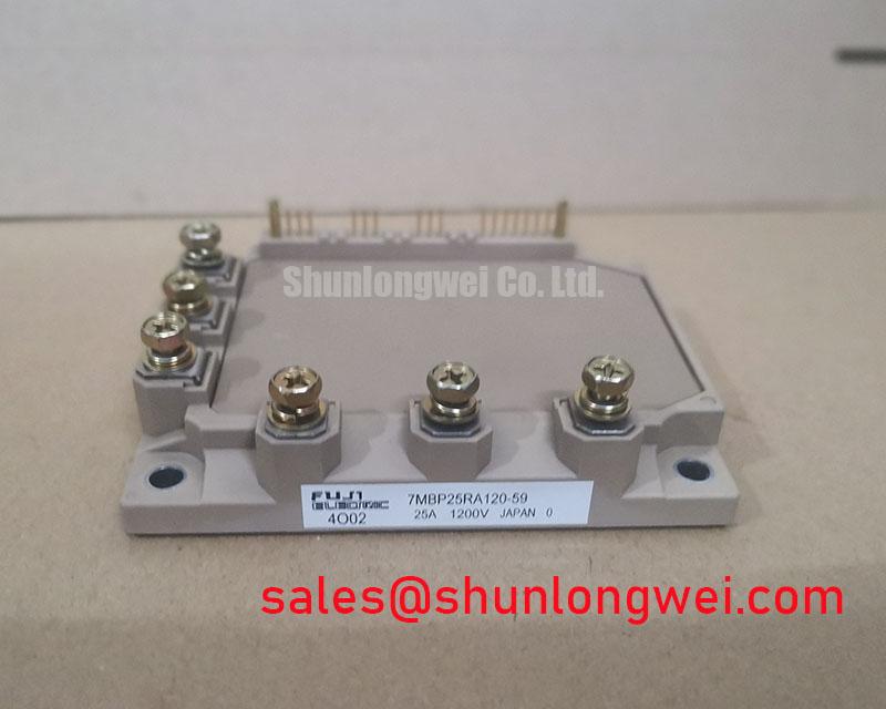
With the DC link discharged and the drive isolated, compare the terminal markings and cold-state measurements of the installed module with the equipment service documentation before evaluating 7MBP25RA120. The supplied product specification identifies it as a Fuji Electric 25.0 A module (Official Specification). “Standard Industrial Rating” does not establish a numerical voltage limit; obtain the original model datasheet before setting DC-link, gate-drive or protection limits.
For an industrial drive, begin with the measured DC-link voltage and capture the collector voltage during switching. The steady bus reading alone will not reveal turn-off overshoot caused by stray inductance. As a Design Consideration, keep the commutation path compact and assess peak voltage under the equipment’s operating conditions against the model-specific limit confirmed in the original datasheet. The required margin is a system decision, not a value established by the 25.0 A current rating.
At elevated sites, insulation clearance and the relationship between operating voltage and single-event burnout risk deserve separate review. Terrestrial neutron exposure cannot be converted into a defensible FIT figure for 7MBP25RA120 without model-specific evidence and an applicable operating profile. Inspect terminal spacing and surrounding conductors against the equipment’s insulation design; use the broader Power Electronics Masterclass for the system-level reliability context. Fuji Electric’s power semiconductor and IPM information provides manufacturer context, but does not replace the original rating sheet for this part.
Assembly Integrity and Layout Architecture for 7MBP25RA120
Before fastening a replacement module, check the heatsink for contamination, raised edges and flatness errors, then examine how the module sits without forcing it against an uneven surface. Apply thermal interface material uniformly rather than assuming a nominal film thickness will compensate for an unknown baseplate profile. Tighten the mounting hardware progressively in the sequence and to the torque specified by the applicable module and equipment documentation. These are assembly Design Considerations; no baseplate curvature, interface thickness or screw torque is established by the supplied product specification.
Field alert: Do not energize the drive until the module mounting and electrical connections have been checked against the original equipment instructions.
Trace the actual rectifier, DC-link, inverter and any braking connections on the drive schematic before transferring wiring. Fuji Electric’s PIM 7-Pack information is useful for understanding the module family, not for assigning unverified terminals to 7MBP25RA120. Where a drive uses another module elsewhere in its power path, 7MBR50SA120-50 can be examined as a separate topology reference; its connection scheme must not be copied without checking the equipment drawing. If the high-side driver uses a bootstrap supply, designers should size it from the confirmed gate-charge data, driver consumption, switching pattern and allowable supply variation.
Field Diagnostics and Commissioning: Gate-Voltage Spikes
A gate-voltage excursion during the opposite switch’s transition may indicate capacitive coupling, gate-loop impedance or a measurement setup issue. Probe the gate and emitter at the relevant module terminals with a suitable differential measurement arrangement, then compare the waveform with a known-good signal path. As a Design Consideration, a short, low-inductance gate return and appropriate damping can help control ringing; the final layout and component choices require switching tests on the assembled drive.
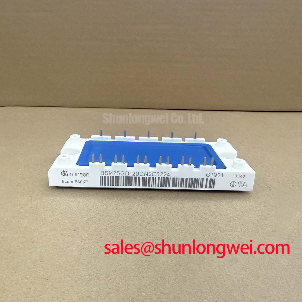
Review the driver schematic before considering an active Miller clamp or negative gate bias. Neither feature, nor its required setting, is established by the supplied specification for this model. Also verify the isolator’s common-mode transient capability against measured switching behavior and inspect the desaturation detection and soft-turn-off sequence against the driver and module documentation. A trip flag alone does not identify cross-conduction as the cause. For a possible replacement comparison, 7MBR50SB120-01 is a reference for checking topology, terminals, ratings, mounting and driver compatibility, not an assumed drop-in equivalent.
7MBP25RA120 Thermal-Electrical Optimization: Braking and Cycling Checks
During commissioning, record the DC-link waveform and module temperature behavior through the machine’s actual acceleration and deceleration cycle. If the equipment has a braking circuit, confirm from its schematic whether the switching device is inside the fitted module or external; the supplied specification does not establish an internal braking IGBT for 7MBP25RA120. Braking-switch and resistor assessment should follow the measured duty cycle, motor and load energy, and the documented limits of the selected parts.
Light industrial automation and multi-joint robotic articulator drives are possible compatibility evaluations, subject to electrical, mechanical and control-interface checks. Repeated thermal swings warrant inspection of cooling contact and operating waveforms, but they do not support a numerical lifetime prediction without applicable test data. The useful acceptance record is the measured temperature and switching behavior of the assembled equipment against its documented limits.