


Content last revised on June 6, 2026
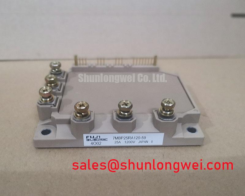
Fuji Electric 7MBP25RA120-59: 1200V, 25A Integrated 7-in-1 IPM for High-Efficiency Motor Drives
An Engineering-Focused Overview of the 7MBP25RA120-59 IGBT Module
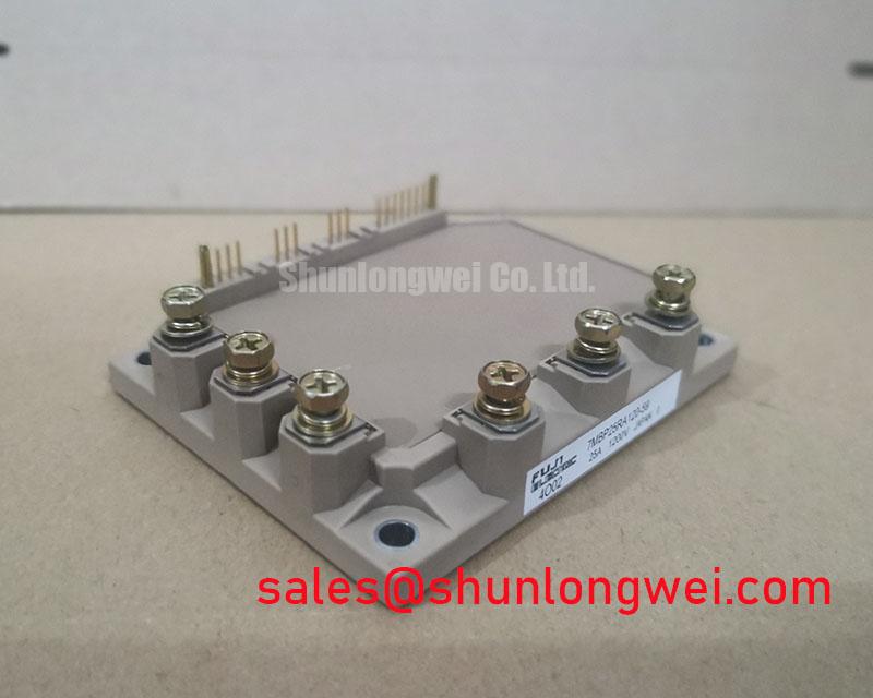
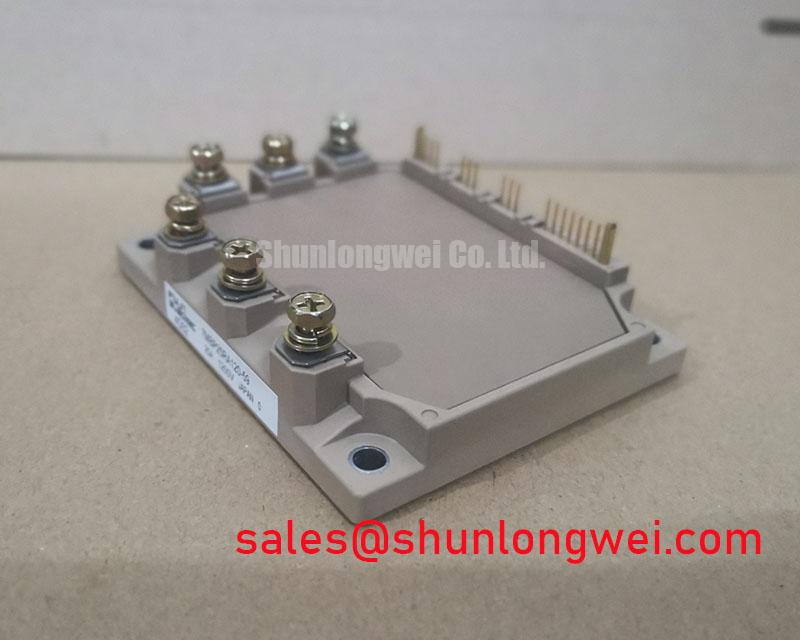
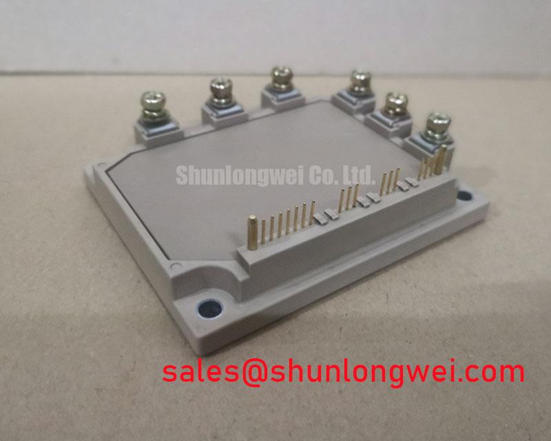
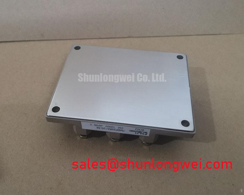
The Fuji Electric 7MBP25RA120-59 is a highly integrated R-Series Power Integrated Module (PIM) designed to streamline the development of compact and efficient power conversion systems. This 7-in-1 module delivers robust performance with ratings of 1200V and 25A, incorporating a three-phase converter, brake chopper, and a full three-phase inverter bridge. Key engineering benefits include significantly reduced conduction losses and simplified thermal management. For engineers working on variable frequency drives (VFDs), the module's high level of integration directly addresses the challenge of minimizing system footprint without compromising on reliability. Best fit for 3-7.5 kW VFDs where thermal performance and efficiency are critical design constraints.
Application Scenarios & Value
System-Level Benefits in Compact Motion Control Systems
The 7MBP25RA120-59 is engineered for applications where power density and efficiency are paramount. Its primary domain is in low- to medium-power industrial motor control, such as Variable Frequency Drive (VFD) systems that power conveyor belts, pumps, fans, and HVAC equipment. In these applications, a common engineering challenge is managing heat dissipation within a constrained enclosure. The module's typical VCE(sat) of 2.7V at its nominal current directly lowers conduction losses, which constitute a significant portion of the total thermal load. Lower losses mean a smaller, less costly heatsink can be used, or alternatively, higher output power can be achieved within the same thermal budget.
The integrated nature of this PIM, combining rectifier, brake, and inverter stages, is a critical enabler for compact designs. It replaces numerous discrete components, reducing PCB complexity, assembly time, and potential points of failure. This consolidation is a key advantage in the design of modern, decentralized servo drives and other motion control systems where space is at a premium. What is the primary benefit of the 7MBP25RA120-59's integration? Simplified design and reduced footprint for compact motor drives. For systems demanding higher power handling, the related 7MBR50VP120-50 provides a 50A current rating within a similar integrated topology.
Key Parameter Overview
Decoding the Specs for Optimized Drive Performance
The following parameters are essential for system design and performance evaluation. The values presented here are based on the official manufacturer's documentation and represent the core electrical and thermal characteristics of the 7MBP25RA120-59.
| Parameter | Symbol | Condition | Value |
|---|---|---|---|
| Inverter Section - Absolute Maximum Ratings (Tc=25°C) | |||
| Collector-Emitter Voltage | VCES | - | 1200V |
| Continuous Collector Current | IC | Tc=80°C | 25A |
| 1ms Pulsed Collector Current | ICP | - | 50A |
| Max Power Dissipation | PC | - | 160W |
| Inverter Section - Electrical Characteristics (Tj=25°C) | |||
| Collector-Emitter Saturation Voltage | VCE(sat) | IC=25A, VGE=15V | 2.7V (Typ.) / 3.3V (Max.) |
| Forward Voltage of FWD | VF | IF=25A, VGE=0V | 2.5V (Typ.) / 3.1V (Max.) |
| Thermal Characteristics | |||
| Thermal Resistance (Inverter IGBT) | Rth(j-c) | Junction to Case | 0.78 °C/W |
| Operating Junction Temperature | Tj | - | -40 to +150°C |
Download the 7MBP25RA120-59 datasheet for detailed specifications and performance curves.
Frequently Asked Questions (FAQ)
What is the engineering significance of the 2.7V typical VCE(sat)?
The Collector-Emitter Saturation Voltage, or VCE(sat), is the voltage drop across the IGBT when it is fully turned on. A lower VCE(sat) means less power is wasted as heat during the conduction phase of a switching cycle. For the 7MBP25RA120-59, the 2.7V value is a direct indicator of its efficiency. Think of it like friction in a mechanical system; lower friction means more of the input energy does useful work. In this case, less electrical energy is converted to waste heat, improving overall drive efficiency and simplifying thermal design.
How does the integrated thermistor improve system reliability?
The built-in NTC thermistor provides a real-time analog of the module's internal temperature. The drive's control logic can monitor this feedback to implement precise over-temperature protection. This is a critical feature for preventing thermal runaway and catastrophic IGBT failure under overload or fault conditions, thus enhancing the long-term reliability of the entire system. How does the integrated thermistor enhance reliability? It enables precise over-temperature protection of the IGBT junctions.
What is the purpose of the integrated brake chopper in this module?
The brake chopper is used in motor drive applications to dissipate regenerative energy. When a motor decelerates rapidly, it acts as a generator, feeding energy back into the drive's DC bus. This can cause a dangerous overvoltage condition. The brake chopper circuit diverts this excess energy to an external braking resistor, where it is safely converted to heat, protecting the DC link capacitors and other components.
Is the 7MBP25RA120-59 suitable for 480V AC line applications?
Yes. A 1200V VCES rating provides the necessary voltage margin for safe operation on 3-phase 480V AC lines. After rectification, a 480V AC line can result in a DC bus voltage of approximately 678V (480V * sqrt(2)). The 1200V rating offers a substantial safety buffer to handle voltage spikes and transients that are common in industrial environments, as outlined in standards like IEC 61800.
Technical Deep Dive
Analyzing the Impact of VCE(sat) on Thermal Design and System Cost
A deeper analysis of the 7MBP25RA120-59's electrical characteristics reveals how a single parameter, VCE(sat), creates a ripple effect through the entire system design. The total power loss in an IGBT module is the sum of conduction and switching losses. At the lower-to-medium switching frequencies typical for motor drives (e.g., 4-10 kHz), conduction losses are a dominant factor. The module's low VCE(sat) is a key lever in reducing these losses, calculated by the formula P_cond ≈ VCE(sat) * Ic * D, where D is the duty cycle.
Consider a practical scenario: a 5.5 kW motor drive. The reduction in dissipated heat from a lower VCE(sat) can mean the difference between requiring a standard, cost-effective extruded aluminum heatsink versus a more complex and expensive solution with forced-air cooling. This is not just a component-level benefit; it translates directly into a lower bill of materials (BOM), a smaller physical enclosure, and potentially higher system-level reliability due to lower operating temperatures. This demonstrates the importance of a holistic IGBT selection strategy that looks beyond the initial component price.
Strategic Design Implications
For engineering teams developing next-generation motor drives, servo amplifiers, or other power conversion hardware, the 7MBP25RA120-59 offers a strategic advantage. Its high level of integration accelerates the design cycle by providing a pre-validated power stage, allowing designers to focus on control logic, firmware, and differentiating features. The balance of 1200V blocking voltage, 25A current capability, and favorable thermal characteristics makes it a compelling foundation for creating reliable and cost-effective industrial automation solutions.