
Content last revised on June 21, 2026
Fuji Electric 2DI200MC-050: A Technical Review of the 200A, 500V Dual IGBT Module
Engineering a Foundation for Reliable Power Conversion
Delivering Robust Performance Through Defined Thermal Characteristics and High Current Capacity
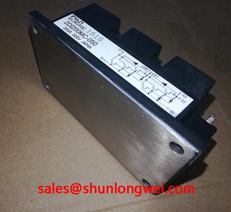
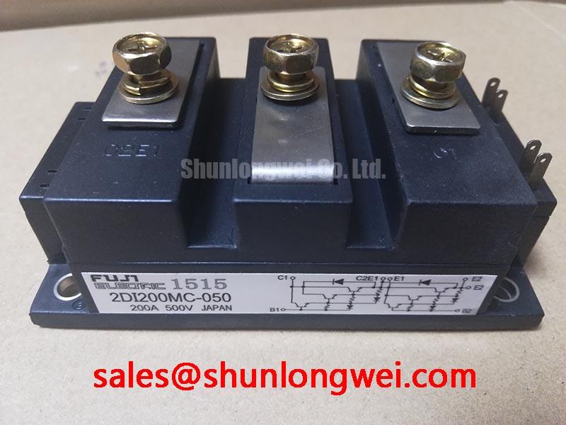
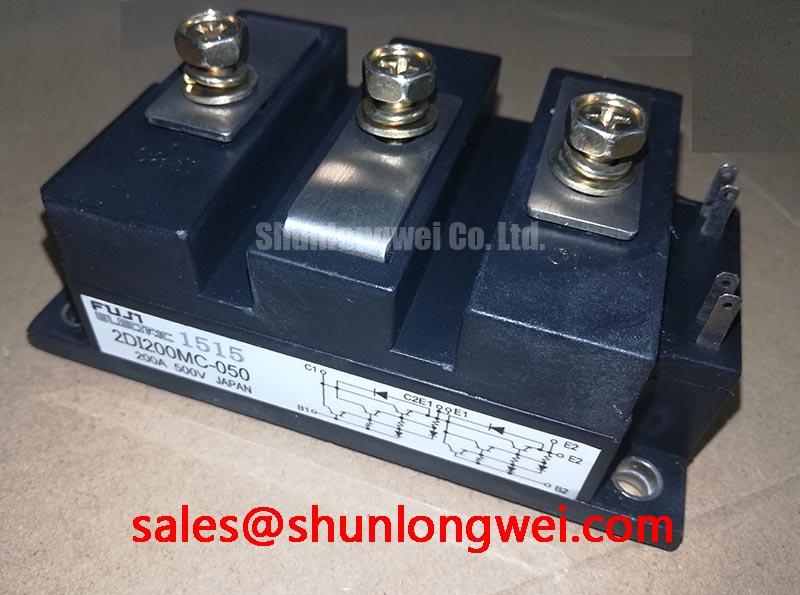
The Fuji Electric 2DI200MC-050 is a dual IGBT module designed to provide a robust foundation for medium-voltage, high-current power conversion systems. Engineered for reliability, this module integrates two IGBTs in a half-bridge configuration, delivering a performance profile defined by its core specifications: 500V | 200A | VCE(sat) 2.5V max. Its key benefits include simplified thermal management and a streamlined power stage design. This module directly addresses the engineering need for a proven, high-capacity switching component in demanding industrial applications. For systems requiring robust performance in the 200-300V DC bus range, the 2DI200MC-050 offers a well-documented and dependable solution.
Application Scenarios & Value
System-Level Benefits in Industrial Motor Control and Power Supply Design
The 2DI200MC-050 is best suited for applications where operational durability and effective handling of substantial current are primary design criteria. Its 500V blocking voltage and 200A continuous current rating make it a strong candidate for systems operating on 200-240V AC lines.
High-Fidelity Engineering Scenario: DC Motor Drives
Consider the design of a DC motor drive for a conveyor system. The primary challenge is managing the high current demand during motor startup and under heavy load, while ensuring the power electronics do not overheat, which could lead to premature failure and costly downtime. The 2DI200MC-050's 200A rating provides ample capacity to handle these current levels. More critically, its specified maximum thermal resistance from junction to case (Rth(j-c)) of 0.18°C/W allows engineers to accurately calculate heatsink requirements. This removes guesswork from the thermal design, ensuring the IGBT junction temperature remains within the safe operating area even under worst-case load conditions, directly enhancing the drive's field reliability.
- DC Motor Drives
- High Power Switching Mode Power Supplies (SMPS)
- DC Chopper Circuits
- Welding Power Supplies
- Uninterruptible Power Supply (UPS) systems
While the 2DI200MC-050 excels in these 500V applications, for systems demanding higher blocking voltage capabilities, the related 2MBI300HH-120 offers a Vces of 1200V.
Key Parameter Overview
Specifications Translated into Engineering Value
The performance of the 2DI200MC-050 is best understood by examining its key electrical and thermal parameters. The following table highlights the specifications that directly influence system design, efficiency, and reliability.
| Parameter | Symbol | Max Value | Conditions | Engineering Value & Interpretation |
|---|---|---|---|---|
| Collector-Emitter Voltage | Vces | 500V | Vge=0V | Provides the necessary voltage margin for reliable operation in power systems with DC bus voltages up to approximately 300V. |
| Gate-Emitter Voltage | Vges | ±20V | - | Defines the standard gate drive voltage requirements, compatible with a wide range of industry-standard gate driver ICs. |
| Continuous Collector Current | Ic | 200A | Tc=25°C | Indicates a high current handling capability, enabling the control of high-power loads and reducing the need for paralleling devices. |
| Collector-Emitter Saturation Voltage | Vce(sat) | 2.5V | Ic=200A, Vge=15V | A lower Vce(sat) means lower conduction losses. At 2.5V, this value is a critical input for calculating power dissipation and overall system efficiency. |
| Thermal Resistance (IGBT) | Rth(j-c) | 0.18°C/W | Junction to Case | This is the module's "thermal fingerprint." A lower value signifies more efficient heat transfer away from the silicon chip, simplifying heatsink selection and improving long-term reliability. |
| Turn-On Time | ton | 1.0µs (typ) | - | Governs the speed at which the switch can activate, influencing switching losses, particularly in higher-frequency designs. |
| Turn-Off Time | toff | 1.5µs (typ) | - | Impacts switching losses and dead-time requirements in half-bridge topologies. A key parameter for optimizing efficiency in inverter and chopper circuits. |
Download the 2DI200MC-050 datasheet for detailed specifications and performance curves.
Technical Deep Dive
The Critical Role of Rth(j-c) in System Longevity
While current and voltage ratings define a module's power handling capacity, its thermal resistance is what dictates its real-world reliability. The 2DI200MC-050 specifies a maximum Rth(j-c) of 0.18°C/W for the IGBT. This parameter can be thought of as the thermal "bottleneck" between the active silicon where heat is generated and the module's baseplate where it is dissipated to a heatsink. A lower number is always better.
To put this into perspective, imagine two pipes of different diameters trying to drain water from a tank. A pipe with a larger diameter (lower resistance) allows water to flow out more easily. Similarly, a low Rth(j-c) allows heat to "flow" away from the junction more efficiently. For an engineer, this means that for every watt of power dissipated as heat, the IGBT junction will only rise by 0.18°C above the case temperature. This predictable thermal behavior is essential for designing a cooling system that guarantees the device operates well below its maximum junction temperature of 150°C, which is the single most important factor in preventing component degradation and ensuring a long service life in industrial equipment like a Welding Power Supply.
Frequently Asked Questions (FAQ)
What is the primary benefit of the dual IGBT (half-bridge) configuration in the 2DI200MC-050?
The integrated half-bridge configuration simplifies the power stage layout by combining two switches into a single, thermally optimized package. This reduces parasitic inductance compared to using discrete components and ensures the two IGBTs are closely matched, which is critical for applications like DC choppers and single-phase motor drives.
How does the Vce(sat) of 2.5V impact my design?
The Vce(sat) directly determines conduction losses, which is the heat generated when the IGBT is fully on. At 200A, the power loss will be approximately P = Vce(sat) * Ic = 2.5V * 200A = 500 Watts. This value is a crucial input for your thermal management calculations and helps determine the overall energy efficiency of your system.
Is a negative gate voltage required to turn off the 2DI200MC-050?
While the datasheet specifies characteristics at Vge=0V for turn-off, using a small negative gate voltage (e.g., -5V to -15V) is a standard industry practice. It provides a greater margin against noise-induced turn-on, improving the system's immunity to dv/dt effects, especially when switching inductive loads.
What is the function of the built-in free-wheeling diode (FWD)?
The integrated FWD provides a path for current to flow when the IGBT is switched off in an inductive load circuit, such as a motor winding. This is essential to prevent a large voltage spike across the IGBT that could damage the device. The co-packaged FWD is optimized for fast recovery (trr) to minimize losses during this phase.
Can the 2DI200MC-050 be used for applications above 20kHz?
Based on its typical turn-on (1.0µs) and turn-off (1.5µs) times, this module is best suited for lower-frequency applications, typically below 20kHz. Pushing to higher frequencies would significantly increase switching losses, leading to excessive heat generation and reduced efficiency. Its design prioritizes current handling and robustness over ultra-high-speed switching.
An Engineer's Perspective on Application
From a design standpoint, the 2DI200MC-050 represents a classic, no-frills power block. It isn't intended to compete on the frontiers of switching speed or power density. Instead, its value lies in its simplicity and predictability. The datasheet provides the clear, fundamental parameters needed for a conservative and robust design. For legacy system repairs or new designs where time-to-market and reliability are more critical than achieving the highest possible efficiency, this module offers a proven, straightforward solution without the complexities of managing the latest-generation, ultra-fast IGBT technologies from manufacturers like Fuji Electric.