





Content last revised on September 29, 2026
VESA vs. JEIDA Data Mapping Alignment & Even/Odd Channel Signal Integrity
| Product Model | AA084VB02 |
|---|---|
| Manufacturer | Mitsubishi Electric |
| Product Category | Industrial Grade LCD/HMI Panel |
| Display Technology | TFT LCD Active Matrix Color Display Module |
| Specification Status | Product identity verified; interface specifications require confirmation |
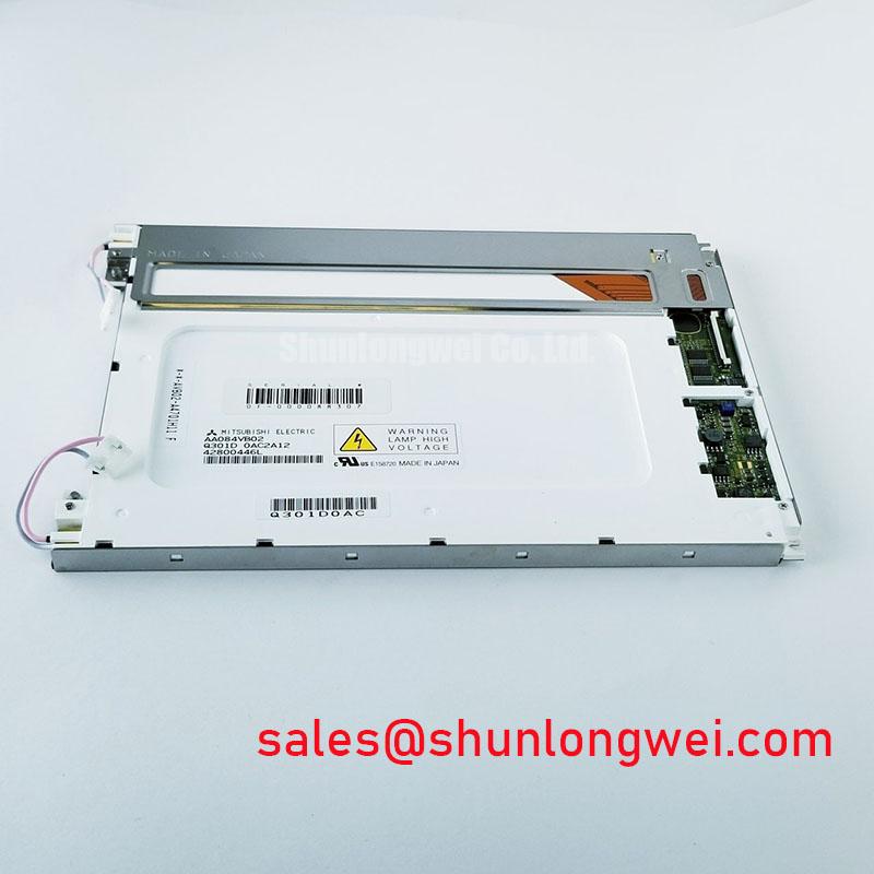
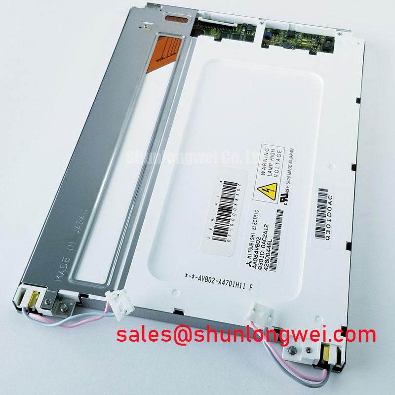
Probe the display supply and interface connector at the panel side, then compare the measured power-on sequence and pixel clock waveform with the host equipment’s known-good display path. The AA084VB02 is identified as a Mitsubishi Electric TFT LCD active matrix color display module, but the supplied factory data does not establish its connector pinout, logic supply voltage, timing table, LVDS channel arrangement, or JEIDA and VESA mapping. Those interface details must therefore be matched against the original panel documentation and the equipment service drawing before a replacement is powered.
Split-screen images, reversed color groups, missing vertical regions, or a stable backlight with unusable graphics should be investigated at the interface rather than assigned to a single cause. Confirm the location of ground, supply, enable, clock, and data conductors first. An oscilloscope comparison between the suspect panel path and a known-good assembly can reveal whether the issue is associated with power sequencing, clock integrity, channel polarity, or data mapping. A logic analyzer may assist with digital activity, but its loading and probe arrangement should not disturb the high-speed display link.
JEIDA and VESA data formats can place the same color information on different bit positions. If the host controller and panel expect different mappings, the image can appear to have incorrect colors even when the clock and differential activity are present. Even and odd channel assignments also require attention because a channel reversal can produce structured image errors rather than a complete loss of display. Check the original cable orientation, connector keying, and any board-level routing labels before changing firmware or rewiring a harness.
For a differential interface, the PCB and cable path should preserve the impedance environment specified by the original system designer. A commonly used engineering reference is a 100 ohm differential path with controlled symmetry, but this is a Design Consideration, not an official AA084VB02 parameter. Keep the pair geometry consistent through connectors and avoid unnecessary stubs. The allowable skew is system dependent and should be verified from the panel timing requirements, host transmitter capability, cable construction, and measured eye opening rather than assumed from a generic display rule.
AGV and forklift telematics installations deserve particular attention at the cable transition between the display housing and the vehicle controller. Repeated vibration can loosen a connector latch or change contact pressure without leaving visible damage. Inspect the locking mechanism, cable bend path, strain relief, and shield termination. When the image intermittently separates into regions, record whether the failure follows vehicle motion, display brightness changes, cold start, or cable movement. That evidence helps distinguish a mechanical connection problem from a signal compatibility problem.
For broader background on panel interfaces, optical construction, and selection factors, engineers can consult The Ultimate Guide to Industrial TFT LCD Technology. External technology references from Tianma NLT Industrial TFT LCD Display Technologies and Winstar Industrial TFT LCD and OLED Display Modules are useful for understanding general interface terminology, but they do not replace the Mitsubishi Electric documentation for this model.
Preventing Localized Light Guide Plate Compression Warp on Dark Screen Fields
Display a uniform dark test image and inspect the panel while gently observing changes caused by the bezel, mounting frame, and cable exit area. Localized bright or dark regions should be documented across several brightness settings and viewing angles. This inspection can expose mechanical loading, uneven frame contact, contamination, or backlight uniformity concerns, but it does not establish one definite failure mechanism without a controlled comparison.
The factory information supplied for AA084VB02 confirms the TFT LCD active matrix display category and Mitsubishi Electric manufacturer, but it does not provide a verified panel outline drawing, active area dimension, mounting-hole pattern, bezel clearance, light guide construction, or recommended fastening torque. The replacement enclosure should therefore be measured from the original assembly. Check the visible aperture, rear frame, connector clearance, gasket compression, and cable exit radius as separate mechanical interfaces.
Do not use the front bezel to compensate for a dimensional mismatch between the display and the enclosure. A frame that presses against the optical stack can create nonuniform dark-field appearance, while insufficient support can allow movement during vehicle vibration. The correct mounting method is determined by the original equipment structure, fastener type, bracket stiffness, gasket material, and panel drawing. Any proposed M3 torque value is a general assembly starting point only and must be validated against the actual chassis and mounting hardware.
Vibration and shock evaluation should use the complete display assembly rather than the loose panel alone. Inspect the bracket for flexure, the fasteners for loosening, and the FPC or board connection for movement after environmental testing. The enclosure should distribute mechanical support around the intended mounting points without transferring concentrated force into the active area. For a forklift display, also review the impact path from the protective cover to the LCD frame because a rigid cover can transmit localized stress during contact events.
Long periods of static HMI content require a separate optical assessment. A persistent image impression can arise from panel operating conditions, drive behavior, temperature, or accumulated use, and the available product facts do not provide a model-specific retention limit or field-life curve. Evaluate the actual interface content, contrast settings, screen saver behavior, and thermal environment in the finished equipment. Avoid presenting a generic backlight lifetime figure as an AA084VB02 factory rating unless it appears in the applicable Mitsubishi Electric document.
Backlight compatibility must also be established from the original panel documentation. The supplied specification does not identify the backlight architecture, input current, driver arrangement, dimming method, or connector assignment. The system integrator should verify whether the existing controller drives the replacement display directly or whether a separate compatible backlight circuit is required. A mismatch in current regulation or enable timing can damage the backlight system even when the image interface appears electrically correct.
When evaluating a related display option, the AA084VD02 may be reviewed as a separate same-size or similar-resolution selection candidate. It should not be treated as a drop-in substitute until the mechanical drawing, connector, optical characteristics, timing, supply requirements, and firmware mapping have been compared with the installed unit.
Industrial EMI Noise Immunity, Chassis Shielding Continuity & Common Mode Ferrite Chokes
Capture the display clock, data activity, and supply rail while the vehicle controller and nearby traction or motor equipment operate under the same conditions that produce horizontal bands or pixel jitter. Compare the waveform at the transmitter, cable entrance, and panel connector. This three-point comparison can show whether the disturbance is coupled through the signal cable, power wiring, chassis reference, or a connector shield termination.
The AA084VB02 product information does not claim independent EMC certification for a complete machine, and a display module cannot by itself establish compliance with an equipment-level CISPR or EN 55011 limit. EMC performance depends on the enclosure, cable routing, grounding strategy, converter layout, motor wiring, filtering, and operating modes of the finished equipment. Shield continuity should be treated as a system design task, with the final result verified through appropriate pre-compliance and formal testing where required.
Inspect the cable shield termination at both the display housing and controller enclosure. A long unbonded shield section can allow common-mode energy to couple into the display path, while an accidental connection between signal return and protective chassis can create unwanted circulating current. The appropriate bonding method depends on the vehicle electrical architecture and safety design. Record the connection arrangement before modification, then test one controlled change at a time.
Common-mode ferrite components may reduce a conducted disturbance when their impedance profile matches the interference spectrum and the cable current does not saturate the material. Their use is an Engineering Recommendation for evaluation, not a guaranteed remedy for AA084VB02 image artifacts. Select and locate any suppression component from measured noise behavior, cable construction, signal integrity impact, and thermal conditions. Verify that the added component does not reduce the display eye margin or interfere with power-on control signals.
Clock jitter and data hold behavior should be evaluated across the actual operating temperature and supply range of the system. The model-specific timing limits, transmitter format, and receiver setup requirements were not included in the supplied factory parameter set, so a generic LVDS timing number should not be assigned to this panel. Use the original timing table and measure the received waveform under normal load, cable flexing, brightness changes, and vehicle electrical transients.
Noise troubleshooting is more effective when the image symptom is logged together with operating state. Record whether the disturbance appears during radio transmission, motor acceleration, charger operation, relay switching, display dimming, or cold start. Check the controller ground reference, DC converter ripple, cable separation from power conductors, and connector retention. If the interference changes when the cable is repositioned, preserve the observation and inspect the physical routing before changing the panel itself.
💡 Pro Tip: Keep high-speed differential pairs away from switching power and motor conductors, and verify signal quality after the final cable routing rather than only on an open test bench.
Wide Temperature Operational Margin and Sub-Zero Liquid Crystal Response
Run a controlled cold-start observation while recording the panel supply, image appearance, response behavior, and enclosure temperature at the display surface. Slow image transitions or temporary contrast changes at low temperature should be compared with the original unit under identical conditions. The supplied factory facts do not specify the AA084VB02 operating temperature range, storage range, gray-to-gray response, heater requirement, seal construction, or brightness variation, so no unverified temperature limit should be assigned to this model.
Liquid crystal response generally becomes slower as temperature decreases, but the amount of change depends on the panel formulation, drive waveform, operating point, and temperature distribution. For an AGV or forklift telematics display, evaluate the complete cold-start sequence rather than judging the panel from a single still image. Confirm whether the host controller waits for the display power and backlight status, whether the first frame is stable, and whether the image recovers during vehicle movement and changing ambient conditions.
Thermal expansion between the display frame, protective window, gasket, bracket, and enclosure can alter mechanical pressure during temperature cycling. Measure the aperture and mounting interfaces at the expected extremes of the finished housing, then inspect for bezel contact, optical nonuniformity, cable strain, and connector movement after cycling. The enclosure should provide environmental protection without trapping heat around the panel or imposing concentrated stress on the active area.
A heater strip or controlled warming function should only be considered after the original display requirements, available power budget, temperature sensors, and thermal safeguards have been established. It is a system-level option, not a confirmed feature or required accessory for AA084VB02. If warming is evaluated, monitor the panel surface rather than relying only on the enclosure air sensor, and verify that the heating method does not create local optical gradients or accelerate aging of nearby components.
FPC reliability deserves a direct inspection during thermal and vibration testing. Confirm that the flexible cable is not folded across a sharp edge, pulled by the enclosure cover, or trapped beneath a bracket. Connector locks should remain fully engaged after assembly, and the cable should retain the bend path defined by the original construction. The exact bend radius and cycle life are model-specific and should be taken from the applicable drawing or supplier documentation rather than inferred from the TFT category.
For sourcing and repair evaluation, retain the original display’s connector orientation, firmware mapping, backlight control method, and mechanical reference points as part of the replacement record. The Mitsubishi Electric identity and TFT LCD active matrix category establish the basic product class, while successful integration depends on matching the complete electrical, optical, mechanical, and environmental interface of the installed equipment.