[Guide]With the popularization of the concept of “carbon neutrality”, industries such as photovoltaics, wind power, and energy storage have once again ushered in the wind. As a common communication interface in these industries, RS-485 often needs to add a protection Circuit to ensure communication stability. This article will introduce a protection circuit scheme for a multi-node environment.
“Carbon neutrality” is a hot topic this year, and one of the key elements to achieve “carbon neutrality” is to vigorously develop new energy sources. In the future construction of my country’s ecological civilization, many sub-sectors in the new energy industry will make outstanding contributions to “carbon neutrality”. For example, a series of industries such as photovoltaic power generation, wind power generation, and inverter energy storage will usher in vigorous development.
As a common interface for communication between devices in the new energy field, the RS-485 bus often needs to add peripheral protection
Circuits in applications to resist the effects of high-level static electricity or surges, and to ensure the stability of its own communication. However, engineers usually use gas discharge tubes and TVS tubes to build protective circuits. The circuit has a high junction capacitance, which will affect bus communication when there are many nodes. In response to this problem, this article will introduce a low-junction capacitance peripheral circuit design reference.
This article will focus on the RS-485 related bus protection circuit scheme.
Commonly used RS-485 protection circuit
Figure 1 Protection circuit 1
In the protection circuit shown in Figure 1, the gas discharge tube discharges most of the surge current at the interface, the common mode inductance filters out the interference of the common mode signal, and the TVS further reduces the residual pressure behind the gas discharge tube to protect the subsequent stage Circuit. The RSM485ECHT module application shown in Figure 1 can achieve electrostatic contact ±8kV, common mode surge ±4kV, differential mode surge ±2kV, and meet the requirements of most industrial sites for RS-485 node static electricity and surge levels.
Although the protection circuit shown in Figure 1 has strong protection capabilities, its junction capacitance is relatively large. The junction capacitance of A-RGND or B-RGND is about 2.5nF. When there are many nodes on the bus, the protection circuit of Figure 1 is used for networking. , The electric capacity of the bus is large, signal reflection and signal edges tend to be flat, which makes the signal quality worse, and even leads to abnormal communication.
Signal reflection problems caused by bus capacitance
When the signal is transmitted on the communication line and reaches the protection circuit on the RS-485 node, the junction capacitance of the protection circuit changes the instantaneous impedance of the signal. Part of the signal will be reflected, and the other part will be distorted and continue to propagate.
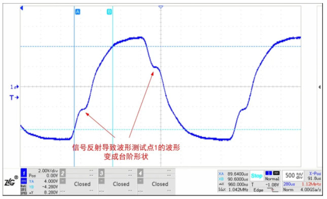
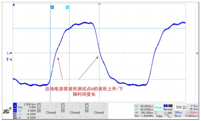
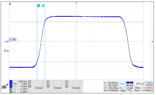
Figure 2 shows the RSM485ECHT single node sending waveform, Figure 3 is a schematic diagram of the RS-485 bus connected to 6 protection circuits, the distance between each node is about 30cm, and the twisted pair is used for hand-in-hand connection, Figure 4 and Figure 5 They are the waveforms of 6 waveform test points 1 and 6 of the circuit shown in Figure 1 (the positions marked in Figure 3) connected to the bus. The rise/fall time of the waveform becomes longer, and the waveform of the waveform test point 1 changes. It became a step shape.
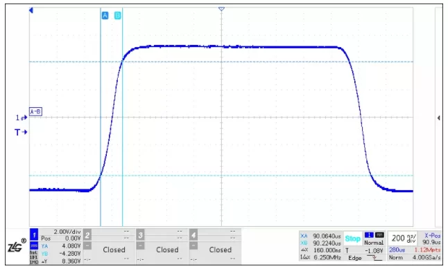
Figure 2 RSM485ECHT single-node RS-485 interface differential waveform
Figure 3 Schematic diagram of the bus connection with 6 protection circuits
Figure 4 RSM485ECHT connected to 6 protection circuit waveform test point 1 waveform
Figure 5 RSM485ECHT connected to 6 protection circuit waveform test points 6 waveforms
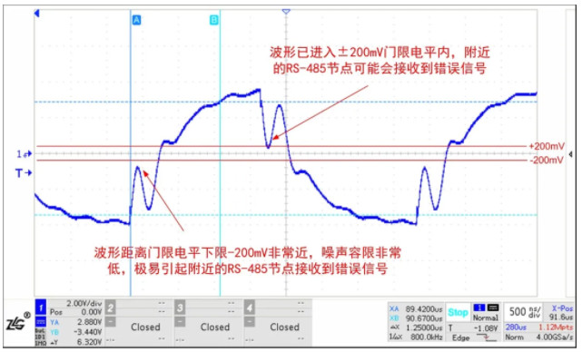
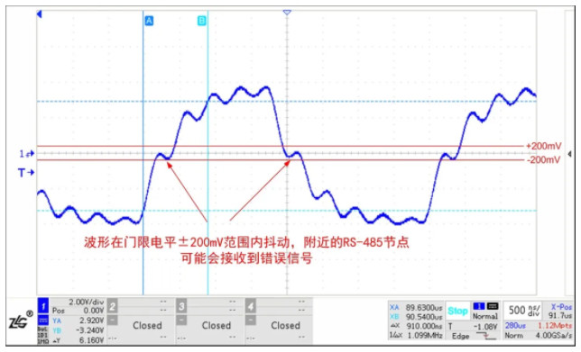
The RS-485 interface of RSM485ECHT has strong driving ability. The following is the test waveform of the commonly used RS-485 transceiver chip in the market under the same test conditions. It can be seen that the waveform has been severely disturbed, and the reflected waveform has reached the RS-485 chip. Near the threshold level, it may cause abnormal communication. Therefore, a transceiver with strong driving capability should be selected in practical applications.
Figure 6 A certain RS-485 transceiver is connected to 6 protection circuit waveform test point 1 waveform
Figure 7 A certain RS-485 transceiver is connected to 6 protection circuit waveform test points 6 waveforms
Low junction capacitance protection circuit
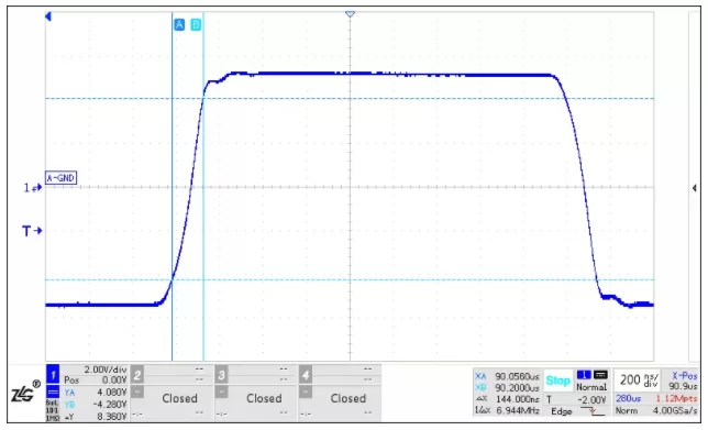
When the number of communication nodes is large, the protection circuit shown in Figure 8 can be used. The junction capacitance of A-RGND or B-RGND is only 20pF. Although the junction capacitance of TVS is larger, the junction capacitance of ordinary diodes is very small. The junction capacitance of the diode is in a series relationship, so the junction capacitance of the protection circuit can be reduced. Use Figure 8 for the networking shown in Figure 3. The waveform of test point 1 is shown in Figure 9, and the waveform of test point 6 is shown in Figure 10. The waveform has basically not changed.
Figure 8 Protection circuit 2 (low junction capacitance)
Figure 9 RSM485ECHT connected to 6 protection circuits 2 waveform test point 1 waveform
Figure 10 RSM485ECHT connected to 6 protection circuits 2 waveform test points 6 waveforms
Summarize
The protection circuit mounted on the bus will change the instantaneous impedance of the signal, resulting in signal reflection. When there are more nodes on the bus, the bus has a larger capacitance, which will interfere with the bus waveform and affect the quality of the communication signal. In order to reduce the impact of the protection circuit on bus communication, in practical applications, you can choose a transceiver with stronger driving capability, and if the protection circuit uses the protection circuit shown in Figure 1, you should choose a low junction capacitance TVS, or you can choose to use Figure 8. The low junction capacitance protection circuit shown.
As a leading domestic bus isolation brand, ZHIYUAN
electronics has launched RSM series isolation transceivers for new energy and industrial fields after 20 years of technology accumulation. RSM series products can effectively solve problems such as bus interference and abnormal communication. Compared with the traditional design, the RSM series products have built-in complete isolation DC-DC circuit, signal isolation circuit, RS-485 bus transceiver circuit and bus protection circuit, with high integration and reliability, which can effectively help users improve bus communication protection grade.
● Baud rate support: 500Kbps, 115.2Kbps, 9.6Kbps, etc.;
● Number of nodes: 256, 128, 32, etc.;
● Number of channels: single, dual, four, etc.;
● Working temperature: -40~85℃ or -40~105℃;
● Isolation voltage: 2500VDC or 3500VDC;
● Mini small size or standard modular package;
● The shell and potting materials meet the UL94 V-0 standard;
● It has low electromagnetic radiation and high immunity to electromagnetic interference.