

Content last revised on October 5, 2026
Transient Dynamics & Electrical Design: Evaluating Thermal Capacitance vs Heat Sink on CM100DC-24NFM
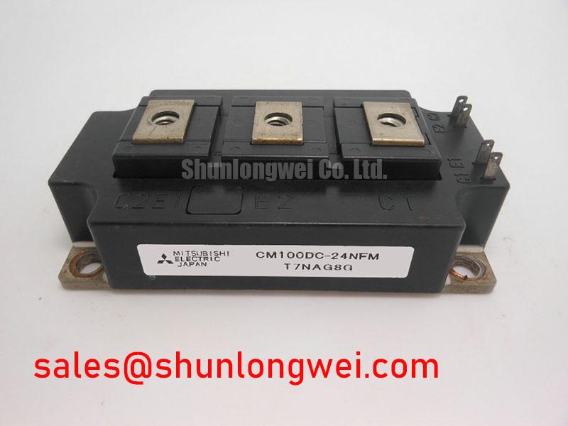
During a pulsed overload, junction temperature does not rise at the same rate as the accessible case or heatsink temperature. Heat moves through the module and its mounting interface over time, so a case reading taken after a current pulse cannot, by itself, establish the peak junction temperature reached during that pulse. For the CM100DC-24NFM, the confirmed 100 A rating should not be treated as a separately verified pulse-current limit. An engineer assessing intermittent duty needs the applicable loss characteristics, transient thermal impedance data, and temperature limits from the exact device documentation before calculating a junction-temperature margin.
As an Engineering Calculation, a transient assessment combines the power dissipated over each part of the switching cycle with the module’s documented thermal response, then adds the effects of repeated pulses and the case temperature at the start of the event. A multi-stage thermal model can represent fast junction heating and slower heat movement toward the heatsink, but its coefficients must come from suitable manufacturer data or a validated test model. Without those inputs, a numerical peak junction temperature would suggest precision that the available specifications do not support. Record current, DC-link voltage, switching activity, case temperature, and pulse duration under a controlled equipment test instead of inferring thermal headroom from the current rating alone.
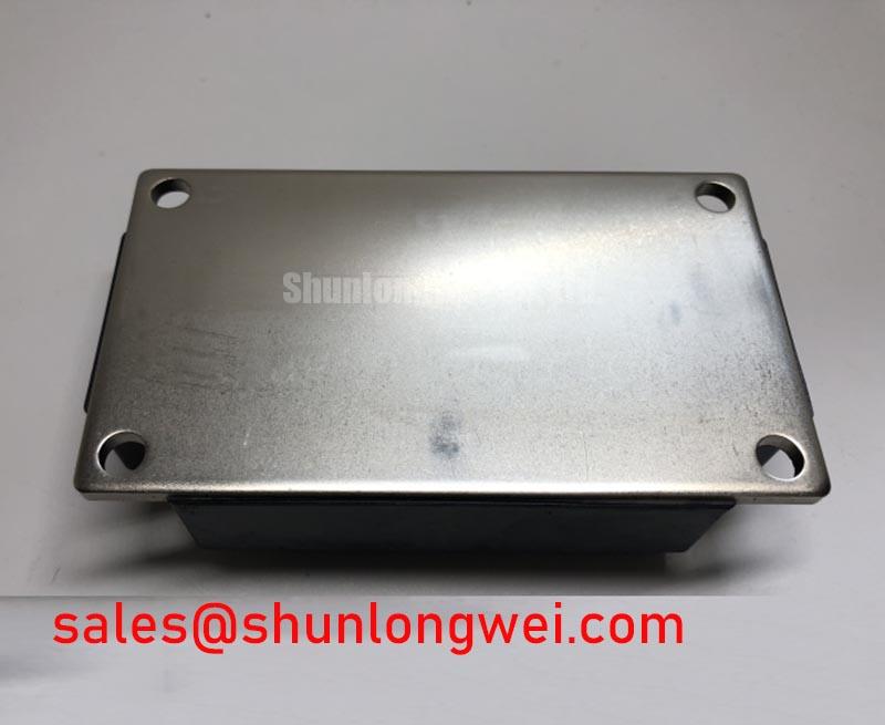
For maintenance, inspect whether the mounting face seats evenly, whether thermal-interface material has deteriorated, and whether dust has restricted the heatsink airflow. These observations matter when a unit reports temperature alarms under loads it previously handled, but none identifies the module as the sole cause. Compare temperature measurements at the same load and airflow conditions, and review the fan, heatsink, and nearby connections before changing a protection threshold. Maintenance Note: Isolate and discharge the DC link before touching module terminals or disturbing its mounting hardware.
Physical and electrical fit also require comparison with the original assembly. Check the footprint, terminal positions, insulation arrangement, gate-drive connections, and permitted clearances against the equipment drawings; the supplied Module package designation does not define those details. The CM100DY-12E is a useful separate reference during a part-number review, not an established drop-in alternative. Its electrical ratings and connections must be checked independently before any substitution is considered.
CM100DC-24NFM Thermal-Electrical Optimization: Auxiliary Emitter Return Trace Separation
Begin at the gate-drive schematic rather than assuming that every emitter-related terminal has the same purpose. If the documented CM100DC-24NFM terminal arrangement provides a separate gate-drive emitter return, trace that connection back to the driver independently of the high-current output path. This is a Design Consideration: voltage developed along a shared power-current path can disturb the effective gate voltage, particularly during rapid switching. The available product parameters do not confirm a dedicated auxiliary or Kelvin emitter terminal, so the exact pinout must be verified before altering a harness or printed-circuit layout.
On an existing assembly, examine the driver return, terminal joints, and nearby power conductors for loose connections or changes made during earlier service. A switching waveform that appears to ring may involve the return path, gate-drive behavior, probing technique, or the power loop. Use appropriately rated differential measurement equipment and compare observations with the equipment’s documented, known-good behavior. Keep the gate-drive loop compact where the approved layout permits, while checking that the revised routing does not compromise isolation spacing or access for service. The final layout and gate-resistance decisions belong to the system designer and require switching tests in the actual assembly.
Desaturation protection should be reviewed with the same caution. Monitoring collector-to-emitter voltage while the IGBT is commanded on can help a driver detect an abnormal high-voltage condition, but its blanking interval, detection threshold, and turn-off response depend on the driver and switching circuit. No desaturation timing or two-stage soft-turn-off specification is established here for the CM100DC-24NFM. If the equipment uses those functions, verify their settings against the driver and module documentation, then examine fault captures for both prompt detection and controlled voltage overshoot. Setting a faster trip without accounting for normal turn-on behavior can create nuisance faults; setting a slower one requires its own protection assessment.
Mitsubishi Electric’s power semiconductor information provides broader context for module integration. Its NX-Series IGBT module information describes a separate product family and should not be used to assign NX-Series construction, terminals, or protection limits to this part number.
CM100DC-24NFM Circuit Protection & Reliability: Calibrating Bi-Directional DC-DC Buck-Boost Conversion
A bidirectional battery converter is one possible system in which an engineer might evaluate a 1200 V, 100 A IGBT module. Those ratings alone do not establish that the CM100DC-24NFM is suitable for a particular converter position. Confirm the actual switch topology, current direction through each device and diode path, switching frequency, cooling method, and fault response from the equipment design. In a commercial string inverter or micro-grid energy-storage cabinet, the battery interface and inverter DC link may impose different duties; the module must be evaluated at the position it would occupy, not against a generic system label.
Repeated charge and discharge demands can produce changing semiconductor losses and case temperatures. As a Design Consideration, assess both the hottest sustained condition and the pattern of temperature swings during peak-shaving duty. The calculation needs the exact device’s conduction and switching-loss information, its applicable thermal data, and measured converter operating conditions. The confirmed 100 A rating is not a promise of continuous converter output at every cooling condition, nor does the 1200 V rating alone establish adequate headroom for switching transients. During commissioning, capture the DC-link voltage and switching peaks under representative charge, discharge, and fault-recovery conditions, then compare them with the applicable device limits.
Protection checks should follow the system’s power path. Verify that current sensing responds in both commanded power-flow directions, that an overcurrent event reaches the gate driver as intended, and that the contactor or upstream control sequence does not leave the converter in an unintended energized state. Review the DC-link capacitor bank, bus connections, and cooling controls as part of that check. The FS100R12N2T4 can be examined as a separate power-module reference when reviewing adjacent converter or inverter stages; its topology, ratings, and circuit role must be confirmed rather than presumed to match or complement this module.
During scheduled service, compare terminal condition and contact temperature with earlier records taken under similar load. Recheck fastening against the equipment maker’s assembly instructions after work on the power stack, and inspect for condensation or contamination around control and power connections. A warm terminal can reflect several conditions, including contact resistance, airflow change, and operating load. Measurements and the maintenance history should guide the next inspection rather than a single visual symptom.
Field Diagnostics & Commissioning: Cosmic Ray Robustness and Voltage Derating in CM100DC-24NFM Topologies
Start a return-to-service check by confirming the installed part number, the discharged-state terminal condition, the gate-driver supply and commands, and the recorded DC-link behavior at the fault. Then inspect the cooling path and mounting interface before repeating an energized test under an approved procedure. A gate fault, overtemperature alarm, or damaged power stage does not establish one cause on its own. Where safe and practical, compare the suspect channel’s waveforms and temperatures with an equivalent operating channel while accounting for probe placement and load differences.
Cosmic-ray effects, single-event burnout, failure-in-time rates, and altitude-related voltage derating cannot be quantified for the CM100DC-24NFM from its 1200 V rating. Such claims require device-specific reliability evidence and defined environmental and operating assumptions. As a Design Consideration, an integrator evaluating an installation at elevated altitude should request applicable manufacturer guidance and review the equipment’s DC-link operating voltage, switching overshoot, cooling, and insulation requirements together. Do not convert a general altitude observation into a part-specific failure rate or fixed derating rule.
For prevention, retain comparable records of heatsink condition, airflow, thermal-interface inspection, terminal work, and fault waveforms. They help distinguish a change in the module’s operating conditions from a change in the surrounding equipment without assigning an unsupported service-life figure. The Power Electronics Masterclass offers additional context for IGBT selection and system reliability; commissioning decisions still need the exact module documentation and measurements from the equipment being serviced.