




Content last revised on October 23, 2026
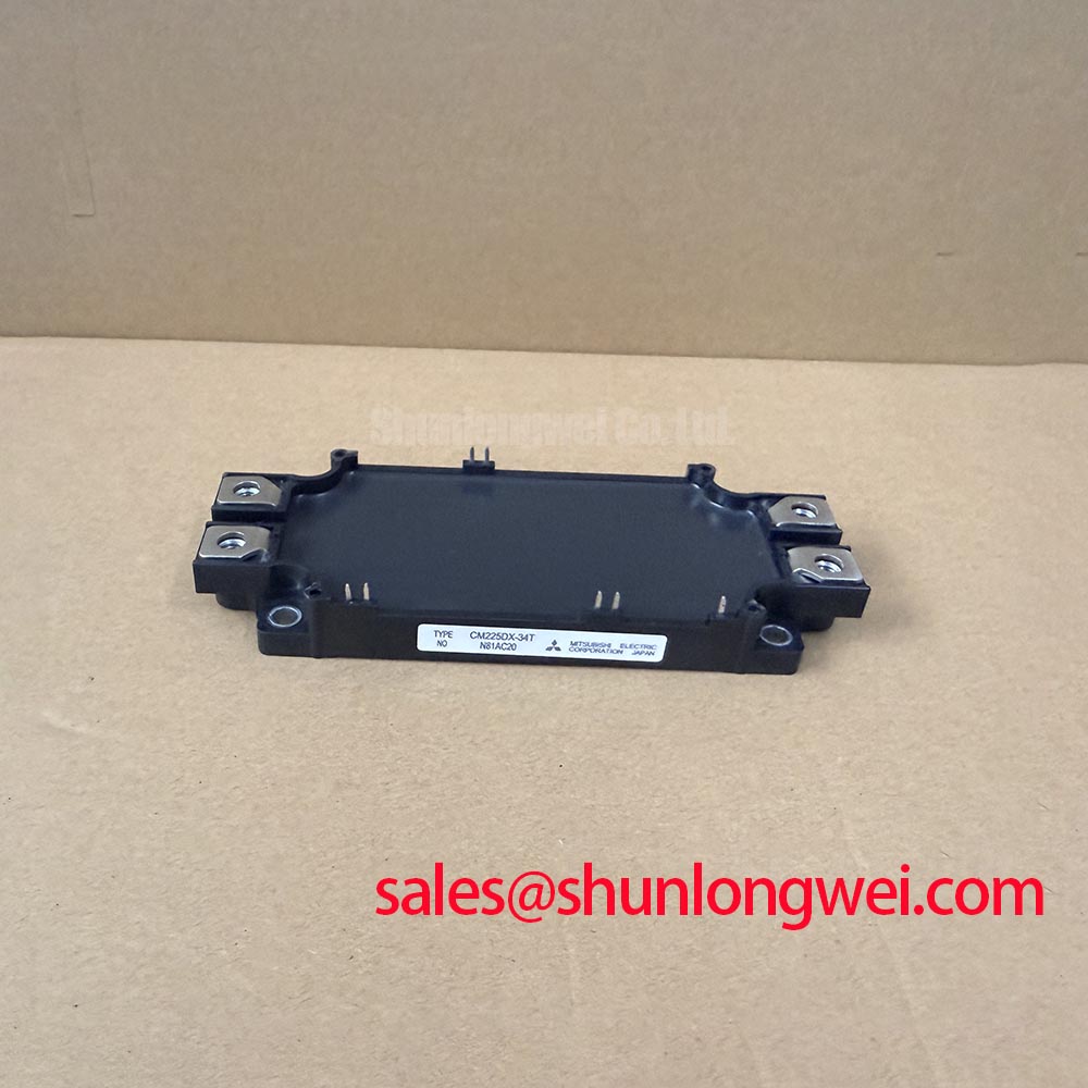
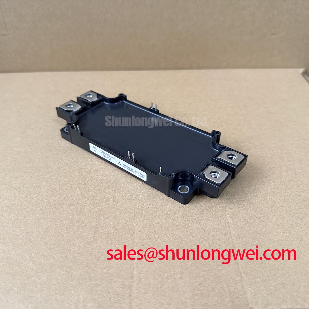
Transient Dynamics and Electrical Design: Atmospheric Neutron Radiation Impact on CM225DX-34T
At elevations above 2000 m, terrestrial neutron exposure becomes a design consideration for high-voltage switching equipment, particularly where a converter operates continuously near its blocking-voltage boundary. Single-event burnout, avalanche stress, and repetitive switching overshoot are system-level reliability questions; the available product parameters identify the module as a 1700 V, 225 A Mitsubishi IGBT module, but they do not provide a model-specific neutron FIT rate or SEB cross-section.
For field evaluation, record the actual DC-link operating range, transient peaks, switching current, pulse width, junction-temperature estimate, and installation altitude. The engineering team can then compare the measured electrical stress with the applicable Mitsubishi application data and the inverter’s derating policy. A 1500 V photovoltaic bus should not be treated as an automatic indication of safe switching margin. Stray inductance, commutation speed, diode recovery, and snubber condition can raise the collector-emitter peak substantially above the steady bus value.
Layout work should keep the high-current commutation loop compact and physically separated from sensitive gate-drive and control wiring. The objective is to reduce parasitic coupling and suppress turn-off overshoot; the final clearance, busbar geometry, insulation system, and switching limits remain determined by the inverter design and its insulation coordination study. At altitude, verify creepage, clearance, contamination level, enclosure pressure effects, and cooling performance as one coordinated review rather than applying a generic altitude multiplier to the module alone.
During troubleshooting, use a properly rated differential probe and observe the collector-emitter waveform at the module terminals, not only at a remote busbar test point. Compare the waveform during startup, normal power transfer, grid disturbance, and controlled shutdown. A sudden increase in overshoot, ringing, or pulse asymmetry may point toward a changed commutation path, loose laminated-bus connection, degraded snubber, driver timing shift, or thermal imbalance. The measurement sequence should be repeated after mechanical service so that electrical symptoms are not confused with an assembly defect.
For background on high-voltage IGBT technologies and application boundaries, engineers may consult Mitsubishi Electric High-Voltage HVIGBT Modules. The reference is useful for technology context, but its general information should not be read as a model-specific SEB qualification for this module.
CM225DX-34T Thermal-Electrical Optimization: Controlling Thermal Grease Pump-Out
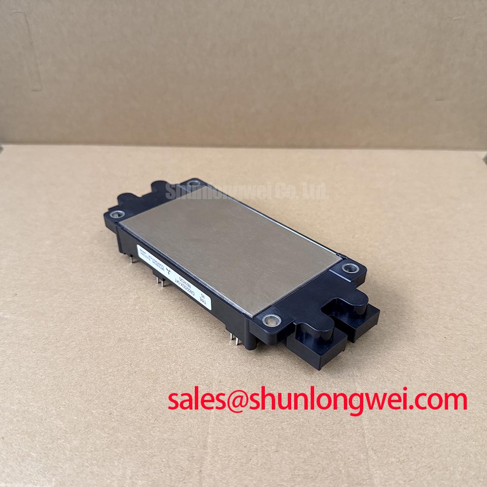
Thermal service begins with isolating all power sources, discharging the DC link according to the equipment procedure, and verifying the absence of hazardous voltage. Remove the module and inspect the copper baseplate for bowing, imprint irregularity, contamination, and local pressure marks. Check the heatsink with a suitable straightedge and cleaning method, then compare the contact pattern after a controlled trial fit. A thick compound layer can conceal poor flatness, increase thermal resistance, and migrate during repeated heating and cooling.
| Item | CM225DX-34T |
|---|---|
| Manufacturer | Mitsubishi |
| Product category | IGBT module |
| Rated voltage | 1700 V |
| Rated current | 225 A under the specified datasheet conditions |
| Mechanical and electrical replacement status | Requires system-level compatibility check |
A separate product listing, such as the FM600TU-2A, does not establish a replacement relationship. Any proposed substitute requires verification of device type, voltage class, current definition, internal topology, terminal geometry, gate characteristics, isolation details, and thermal interface dimensions. A procurement comparison should use the original inverter bill of materials and service drawing rather than the package appearance alone.
Thermal compound should be spread as a uniform, thin interface layer appropriate to the selected material and the measured surface condition. The commonly used engineering target of roughly 50–80 µm may serve as a starting reference for a suitably flat interface, but the compound manufacturer’s instructions and the actual flatness measurement take priority. Avoid using excess material to compensate for a warped heatsink; correct the mechanical surface or replace the unsuitable heatsink.
Switching frequency changes the balance between conduction loss and switching loss. When evaluating operation from approximately 2 kHz to 16 kHz, calculate losses from the real gate resistance, bus voltage, load current, junction temperature, dead time, and switching waveform. Cooling airflow must be checked at the heatsink inlet under enclosure conditions, including filter loading and nearby heat sources. The module’s 225 A rating is not a universal continuous-current guarantee for every frequency, duty cycle, or cooling arrangement.
Benchtop Waveform Tuning: Reinforced Insulation Barrier Integrity
Waveform tuning should start with the isolation barrier and measurement setup, because a probe connection or driver reference error can appear as a gate malfunction. Check the gate-emitter signal at the module terminals, verify the driver return path, and confirm that the oscilloscope reference is appropriate for the switching node. Do not attribute a specified reinforced-isolation voltage or a CMTI value to the CM225DX-34T unless that value appears in the applicable module and driver documentation.
Where reinforced galvanic isolation is required, the barrier must be assessed across the complete gate-drive assembly, including the isolator, power supply, PCB spacing, connectors, and enclosure. A design may establish an isolation withstand target above 5 kV and a common-mode transient immunity target above 100 kV/µs, but these are system engineering requirements, not confirmed product ratings supplied for this listing. Validate them through the relevant safety and functional test plan before assigning compliance to the assembled drive.
False gate pulses often become visible as narrow disturbances during the Miller plateau or during rapid collector-voltage transitions. Investigate the physical return path, driver supply decoupling, isolation capacitance, gate-loop coupling, and control-board routing. The preferred corrective approach is to minimize parasitic coupling and maintain a controlled gate-drive reference, then verify the result with a differential measurement at the module terminals. Do not solve an instability by selecting a random gate resistor without checking turn-on loss, turn-off overshoot, dead time, and thermal impact.
When the converter is connected to a photovoltaic central inverter, compare the upper and lower switching positions under identical load conditions. Unequal waveform timing can indicate driver propagation mismatch, an altered gate path, or an installation problem. Use the known-good phase leg as the reference where available. The test should include controlled current, gradual bus-voltage increase, and a shutdown sequence that confirms the gate remains in its intended state when the control supply changes.
Assembly Integrity and Layout Architecture: Thermal Interface Thickness Control
Mechanical assembly determines whether the module can transfer heat consistently over repeated load cycles. Clean both mating surfaces without scratching them, position the module squarely, and start every fastener by hand before applying the final sequence. A diagonal cross-pattern helps distribute pressure across the baseplate; the actual torque must follow the module drawing, fastener grade, washer arrangement, and heatsink specification.
Where the design uses a controlled interface thickness in the approximate 50–100 µm range, the target should be established by measured flatness and the selected thermal interface material, not by visual appearance. After tightening, inspect the spread pattern from a service sample or use the supplier’s approved verification method. Voids near high-loss regions, edge squeeze-out, or a narrow central imprint may indicate surface curvature, excessive compound, uneven tightening, or a damaged baseplate.
Baseplate curvature compensation must be handled mechanically. Do not force the package flat with excessive torque, and do not use the mounting screws to correct a heatsink that is outside its specified flatness. If a clamping system uses disc springs or another pressure-control method, calibrate the assembled stack against the manufacturer’s force requirement and check spring orientation during service.
Field Alert: Isolate all power sources, including DC-link and control power, discharge stored energy according to the equipment procedure, and verify the absence of hazardous voltage before touching terminals or removing the module. Follow the fastener torque sequence specified for the actual assembly rather than applying a generic torque value.
After installation, inspect terminal seating, busbar alignment, gate connector retention, and insulation barriers before applying power. Use thermal imaging during a controlled load increase to compare phase-leg temperatures, while remembering that a surface temperature pattern is an indicator rather than a direct junction-temperature measurement. Record the baseline waveform, heatsink temperature, airflow condition, and torque verification in the service report so future maintenance can distinguish electrical drift from mechanical rework.
For broader system-level guidance on IGBT selection, switching stress, thermal paths, and reliability planning, see the Power Electronics Masterclass.