
Content last revised on September 13, 2026
CM50DY-12H Circuit Protection and Reliability: Evaluating Transient Thermal Response Against the Heat Sink
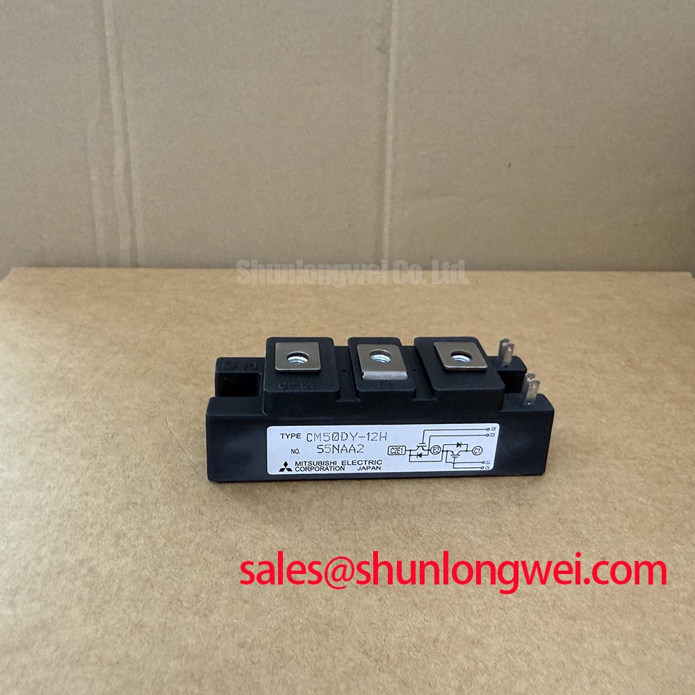
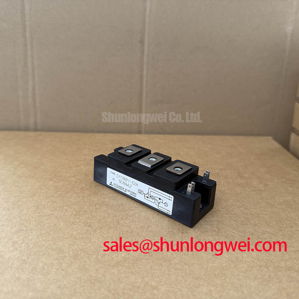
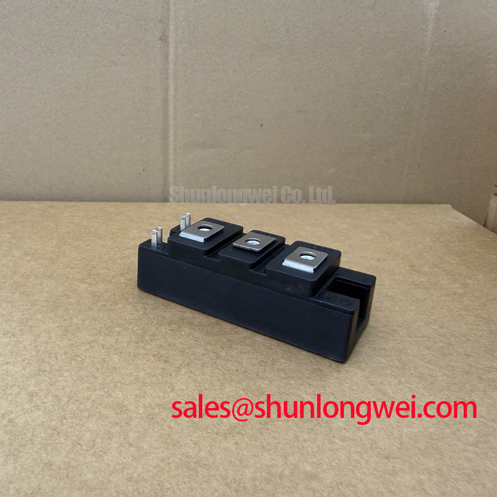
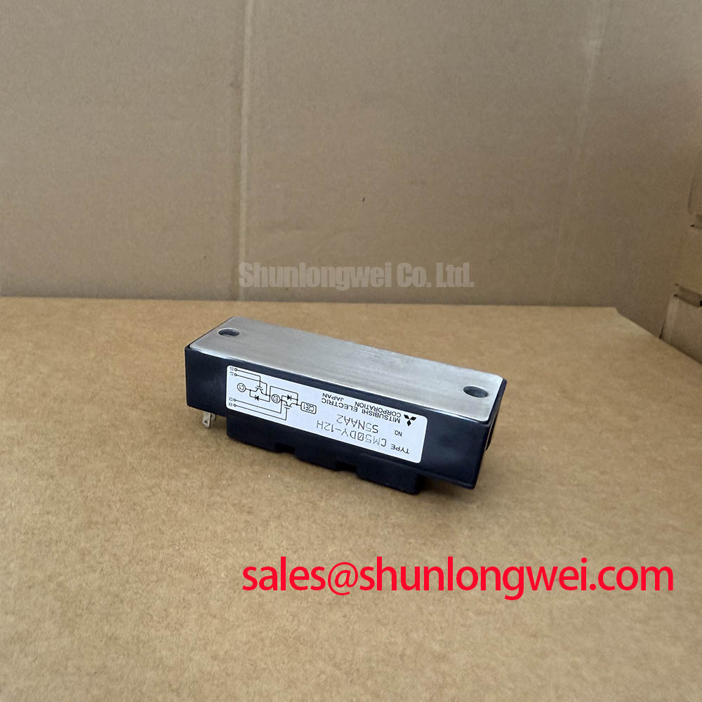
Begin a replacement evaluation by isolating the inverter, documenting the original terminal wiring, and checking the module’s external condition before applying test power. The CM50DY-12H is a Mitsubishi Electric IGBT module with an official rated voltage of 600.0 V, an official rated current of 50.0 A, and a Module package designation. These values define the basic device identity; the complete electrical and thermal limits must be confirmed against the equipment’s original documentation and the applicable Mitsubishi Electric data.
| Manufacturer | Mitsubishi Electric |
| Model | CM50DY-12H |
| Rated voltage | 600.0 V |
| Rated current | 50.0 A |
| Package | Module |
| Potential application | Light industrial automation and multi-joint robotic articulator drives, subject to system verification |
For procurement and repair work, the rating should be treated as an official specification rather than a complete operating prescription. Switching frequency, gate voltage, short-circuit capability, junction temperature limits, transient thermal impedance, isolation characteristics, and terminal assignments should be taken from the correct manufacturer documentation for the exact production version. Mitsubishi Electric’s power semiconductor and high-power module reference provides the appropriate manufacturer context for this class of device.
When a CM50DY-12H is removed from a working inverter, record the original mounting position, thermal interface condition, busbar orientation, and gate-drive cable routing. A visual inspection should cover cracks, damaged terminal hardware, discoloration around the power connections, contamination on the insulating surface, and signs that the heat path has been disturbed. A cold electrical comparison against a known-good assembly can help identify an abnormal terminal relationship, but resistance readings alone do not establish semiconductor health.
Design Consideration: The module’s 50.0 A rating is not a universal permission to operate at 50.0 A under every switching or ambient condition. Conduction loss, switching loss, case temperature, cooling airflow, overload duration, duty cycle, and the thermal resistance of the complete mounting stack all affect junction temperature. The heat sink should therefore be evaluated as part of the electrical design, including its flatness, interface coverage, fastening condition, and ability to remove both repetitive and pulsed heat.
For pulsed overload analysis, engineers commonly represent the junction-to-case path with a transient thermal impedance network formed from multiple thermal resistance and capacitance sections. This approach separates the short pulse response from the slower heat-sink response. The calculated junction temperature should be compared with the applicable manufacturer limit using the actual pulse width, repetition pattern, case temperature, and conduction state. If the original datasheet does not provide the required transient thermal impedance curve, the result should remain a design estimate until validated with temperature measurement and switching tests.
Protection should be coordinated at the system level. A desaturation detector, current sensor, fuse, or controller-based shutdown may respond at different points in a fault event, and the suitable method depends on the gate driver, DC link, load, and fault energy. For a battery-connected bidirectional DC to DC converter, repeated charge and discharge cycles can create changing thermal gradients. The system designer should verify the worst-case junction temperature in both power-flow directions and assess whether the cooling arrangement handles the duty cycle without assuming a specific field lifetime.
Keep high-current conductors physically separated from the gate-control return path, and minimize the commutation loop area to reduce induced voltage during turn-off. Any clearance and creepage requirement must be selected from the working voltage, pollution environment, insulation system, and applicable equipment standard. Pro Tip: Disconnect the DC link and verify the discharged state before unplugging gate-drive or power wiring.
Field Diagnostics and Commissioning: Transmission-Line Impedance Mismatch in CM50DY-12H Topologies
Long motor cables and fast inverter edges should be treated as a distributed network rather than as an ideal connection. Reflections caused by cable impedance, motor input characteristics, termination conditions, and switching speed can create terminal overshoot that is substantially higher than the nominal DC-link voltage. In some installations, the peak can approach twice the DC-link value, but the actual result is system-dependent and must be measured at the module and motor terminals.
During commissioning, use a suitably rated differential probe and observe collector-emitter voltage, phase current, gate-emitter voltage, and the driver return reference together. Compare the waveform with the inverter unloaded, connected to the motor, and operating through the intended cable arrangement. A ringing pattern may indicate impedance interaction, excessive parasitic inductance, probe-loop error, or gate-drive instability; it should not be assigned to one cause without checking the complete signal path.
Output filters, common-mode chokes, dv/dt filters, and motor-side termination networks are engineering recommendations whose values must be determined from cable length, motor insulation limits, switching behavior, leakage current, acoustic requirements, and thermal loss. The correct objective is to control peak voltage and edge stress while preserving acceptable inverter efficiency and motor performance. Designers should verify the resulting peak margins against the DC-link voltage during switching tests rather than selecting a filter from the module current rating alone.
The gate loop deserves the same measurement discipline. The source and sink capability of the isolated driver must be adequate for the selected gate charge and switching target, while the gate-return conductor should follow the intended power-emitter reference as closely as the module layout permits. An external gate resistor can damp oscillation, but its value is a typical starting point for bench tuning, not an official CM50DY-12H parameter. Tune it while monitoring gate voltage, collector-emitter overshoot, switching loss, and cross-conduction behavior.
For a replacement investigation, compare the original gate resistor network, driver supply arrangement, dead-time behavior, and protection response before changing the module. The CM100DY-12E may appear in the same broader selection discussion, but its ratings, pin arrangement, switching behavior, and thermal requirements must be checked independently before any cross-model evaluation.
Field Diagnostics and Commissioning: Static and Dynamic Current Distribution in CM50DY-12H Topologies
Current distribution becomes a central concern when multiple switching paths, paralleled devices, or several inverter legs share a DC-link structure. A positive temperature coefficient of on-state voltage is a design consideration that can support static current balancing in suitable IGBT arrangements, because a warmer device may naturally develop a higher conduction voltage. This behavior does not remove the need for matched electrical paths, thermal symmetry, and measured validation.
Dynamic sharing is governed by much faster variables. Differences in gate-loop inductance, driver propagation delay, common-emitter impedance, busbar geometry, and stray inductance can cause one path to turn on or off earlier than another. Route the gate-drive conductors with consistent geometry and keep power commutation paths symmetrical where the topology requires parallel operation. If the module’s terminal configuration includes an auxiliary emitter or separate control return, the system integrator should verify its exact function and pin assignment from the original Mitsubishi Electric documentation before using it as a measurement reference.
At the bench, measure each relevant current path with the same probe type and bandwidth, then compare turn-on delay, current rise, turn-off behavior, and voltage overshoot under equivalent operating conditions. A difference in static current does not necessarily prove a defective module; it may also reflect unequal thermal contact, busbar resistance, driver mismatch, or sensor placement. Likewise, a balanced low-frequency current waveform does not prove that the paths share dynamic switching stress evenly.
In a robotic articulator drive, repeated acceleration and deceleration can produce bidirectional power flow and changing phase-current patterns. Designers should evaluate the highest current combination, regeneration behavior, braking sequence, and DC-link control together. Any current derating should be based on the measured case temperature and the verified thermal model. The related CM50DY-28H can be reviewed as an adjacent rectification or complementary-stage reference, but it should not be treated as an automatic electrical substitute for the CM50DY-12H.
Benchtop Waveform Tuning: Mitigating Stress with Negative Gate Bias and Active Miller Clamping on CM50DY-12H
False turn-on during a high-side or low-side switching event is commonly investigated by observing the inactive device’s gate-emitter voltage while the opposing device changes state. The Miller current flowing through the gate-collector capacitance can lift the inactive gate reference, especially when the common-emitter path contains parasitic inductance or when the driver return is exposed to common-mode ground bounce.
Negative gate bias is an engineering recommendation that may improve off-state immunity in a suitable isolated driver, but the permitted gate-emitter range, driver supply arrangement, insulation coordination, and power-up sequence must be verified for the exact module and driver combination. A negative level should never be selected from a generic IGBT rule. The bench test should confirm that the negative bias does not exceed the manufacturer’s gate-emitter limits during ringing, startup, shutdown, or fault recovery.
An active Miller clamp can provide a low-impedance off-state path when the driver detects a high dv/dt event. Its effectiveness depends on the clamp connection, driver timing, gate-loop layout, emitter reference, and the point at which the clamp becomes active. Designers should place the clamp return close to the intended gate reference and validate the circuit with the real busbar, load, cable, and driver isolation structure. The test target is controlled gate behavior without excessive switching loss or unwanted interaction with desaturation protection.
Short-circuit protection requires careful coordination between desaturation detection, blanking behavior, soft turn-off, and the module’s short-circuit withstand specification. A soft shutdown can reduce voltage overshoot by limiting the rate of current interruption, but it also changes fault energy and device heating. The suitable timing is therefore system-determined and must be verified with a controlled test method, current limiting, appropriate probing, and the applicable manufacturer limits.
Use the The Ultimate IGBT Knowledge Base as an additional practical reference when reviewing gate-loop inductance, Miller coupling, and switching-stress measurements. The CM50DY-12H remains identified by its official 600.0 V voltage rating, 50.0 A current rating, and Module package; final integration acceptance belongs to the equipment designer’s verified electrical, thermal, and protection tests.