Content last revised on November 2, 2026
Assembly Integrity & Layout Architecture: Implementing Baseplate Isolation Breakdown Testing for CM50DY-12E
Disconnect the power stage, verify that the DC link is discharged, and isolate the module terminals from parallel circuit paths before comparing cold-state resistance readings. On a Mitsubishi Electric CM50DY-12E, record the terminal identification and connection orientation before removing busbars or gate wiring. A low reading through an assembled converter can include capacitors, driver components, or adjacent semiconductor paths; it is not sufficient evidence to condemn the module.
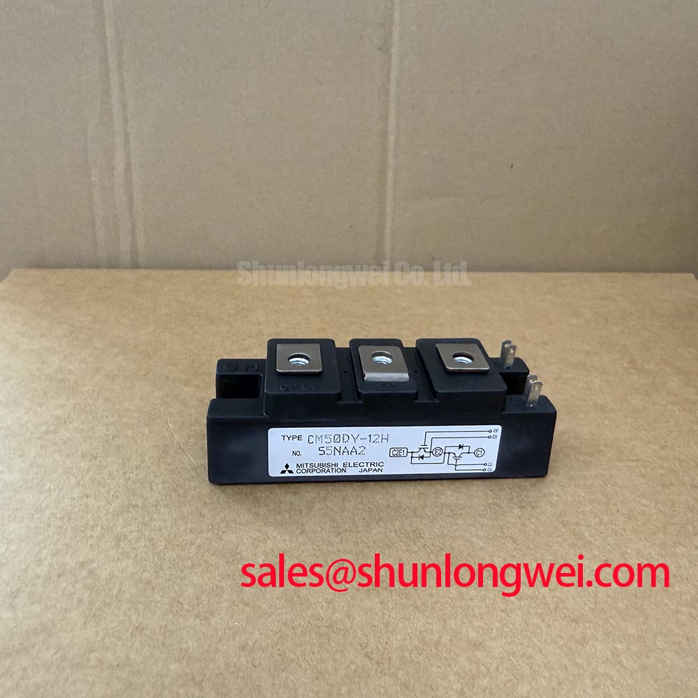
The CM50DY-12E IGBT module has an official collector-emitter voltage rating of 600 V with gate-emitter voltage at 0 V, and an official collector current rating of 50 A at a case temperature of 25°C. These conditions belong with the ratings when checking a replacement against an equipment service record. Photograph the installed connections, inspect terminal seating surfaces, and retain the original insulation barriers for comparison during reassembly.
Separate the module from connected electronics before assessing terminal-to-baseplate insulation. Gate drivers, sensing circuits, suppression components, and protective-earth connections can alter the measurement path or be exposed to an inappropriate test voltage. Identify exactly which conductors the equipment service procedure requires to be connected together, which remain isolated, and where the test instrument return belongs before applying any insulation-test stimulus.
The official isolation voltage specification is 2500 Vrms AC for 1 minute. This is a dielectric withstand specification under its stated conditions, not a recommended routine field-test setting. It does not establish a DC insulation-resistance acceptance threshold, nor does it authorize substituting a high-voltage DC megohmmeter test for the specified AC test. Repeated withstand testing should follow the applicable manufacturer and equipment service procedures rather than becoming an automatic step after every removal.
Design Consideration: Inspect the accessible insulation surfaces for conductive residue, moisture, damaged barriers, and contamination around terminal supports. Clean using materials compatible with the assembly, allow the surfaces to dry, and reassess the isolated measurement path. A change after cleaning can help localize a surface-related leakage path, but it does not prove the condition of concealed insulation. External inspection and terminal measurements should not be presented as confirmation of a particular internal ceramic material or construction.
Check the installed clearance around busbar edges, mounting hardware, and grounded heatsink features against the equipment drawings. Repositioned conductors, displaced sleeves, or trapped debris can change the external insulation geometry even when the replacement module seats correctly. Creepage and clearance requirements depend on the assembly’s working voltage, environment, and applicable insulation-coordination requirements; the module’s isolation rating alone does not define the required distances throughout the converter.
For cold electrical screening, use the circuit diagram to identify the intended semiconductor paths and compare corresponding positions under the same instrument polarity. Record readings only after they settle, with gate handling controlled according to the service procedure. Unexpected asymmetry warrants isolating the relevant path further. A handheld meter can reveal some gross shorts or leakage symptoms, but it cannot establish switching performance, dielectric withstand, or serviceability under load.
Replacement assessment should also preserve the electrical and mechanical interface, not simply the voltage class. The CM300DY-12HE is a separate model for cross-model specification comparison, not an automatic substitute for the CM50DY-12E. Compare the terminal arrangement, mounting drawing, driver requirements, switching characteristics, and thermal interface before considering a change. For a high-dynamics multi-axis CNC or robotics servo drive, compatibility also requires checking the original power-stage topology and protection coordination against the equipment documentation.
CM50DY-12E Circuit Protection & Reliability: Calibrating Baseplate Thermal Grease Layer Control
Remove old interface material from the baseplate and heatsink contact area without scratching either mating surface. Inspect for raised burrs, embedded particles, damaged threads, and uneven contact marks before applying fresh thermal interface material. A visible deposit ridge or an unseated mounting face can compromise heat transfer even when the fasteners appear tight.
The official maximum junction-to-case thermal resistance is 0.52°C/W per IGBT. The official total power dissipation rating is 240 W per IGBT at a case temperature of 25°C, and the official maximum junction temperature is 150°C. These specifications describe particular thermal boundaries; the junction-to-case value does not include the interface between the module and heatsink or the heatsink’s path to the surrounding environment.
Design Consideration: Apply a controlled, uniform interface layer using a process appropriate to the selected material and mounting surfaces. The objective is to fill surface irregularities without introducing an unnecessarily thick thermal barrier. Establish thickness through the thermal material instructions, mounting guidance, and assembly validation rather than adopting a generic micrometre value as a CM50DY-12E specification. Where the maintenance procedure permits it, a controlled contact-pattern inspection can help identify incomplete coverage or excessive displacement.
Baseplate curvature and heatsink flatness need separate attention. Thermal grease is not a structural repair for a distorted mounting surface. If the assembly rocks before tightening, investigate the mating geometry and foreign material rather than drawing the baseplate down forcibly with the screws. Excess interface material can conceal poor contact during assembly while leaving the underlying mechanical problem unresolved.
Seat the fasteners progressively so that clamping develops evenly across the mounting face. A balanced tightening sequence can help avoid loading one corner prematurely, but the final sequence and torque must follow the applicable mounting instructions and hardware specification. Distinguish baseplate mounting fasteners from electrical terminal fasteners: their functions and allowable loading are not interchangeable.
Field Alert: Do not use mounting screws to pull an uneven baseplate onto the heatsink; correct the seating condition and follow the specified fastening procedure.
The official maximum collector-emitter saturation voltage is 2.7 V at 50 A collector current, 15 V gate-emitter voltage, and 125°C junction temperature. Keep those test conditions attached to the value when assessing conduction loss. It is not a universal voltage drop across every operating current or temperature, and the stated gate voltage is a characterization condition rather than a complete gate-drive prescription.
During controlled recommissioning, record case or heatsink temperature together with load, cooling conditions, and measurement location. A heatsink reading is not a direct junction-temperature measurement. If temperature rises unexpectedly, examine interface contact, cooling performance, operating current, and switching behavior together. Repeated overload trips should not be addressed by assuming a fixed cooling delay or an undocumented surge-current allowance; the equipment protection strategy must account for the actual thermal state and applicable semiconductor limits.
Benchtop Waveform Tuning: Mitigating Stress via Transmission Line Impedance Mismatch on CM50DY-12E
Measure the switching-node waveform and motor-terminal waveform separately when investigating cable-related voltage stress. Use appropriately rated differential probes, suitable bandwidth, and a connection arrangement that minimizes measurement-loop pickup. Document the probe reference and measurement location: an inverter-side collector-emitter transient and a reflected pulse at a remote motor terminal are different observations and should not be treated as interchangeable.
Design Consideration: Long motor leads can behave as transmission lines when switching transitions are fast relative to cable propagation time. An impedance discontinuity at the load can produce reflected waves and increase terminal stress. The resulting peak depends on cable characteristics, termination, pulse timing, and edge behavior; a fixed multiplication of DC-link voltage is not a CM50DY-12E specification. Compare waveforms at the relevant locations before attributing a drive fault to cable reflection.
Keep local commutation overshoot distinct from the cable effect. Parasitic inductance in the converter’s current loop can generate additional voltage during rapid current change, while output-cable reflections involve propagation and load termination. The linked technical discussion, Mastering Power System Dynamics, provides context for reviewing stray inductance and snubber behavior. Any changes should be validated against measured device stress and the equipment’s switching conditions, rather than judged from a cleaner-looking trace alone.
Output filters and chokes require system-level selection. If measurements support a cable-reflection problem, assess the motor insulation requirements, cable arrangement, operating frequency range, filter losses, and control-loop interaction before choosing an output network. An output choke is not automatically equivalent to a dv/dt filter, and neither should be assumed to correct excessive overshoot inside the module’s local commutation loop.
Review freewheel-diode recovery when current commutates between switching paths. Recovery behavior can influence current peaks, ringing, and conducted noise, but softness factor, reverse-recovery charge, and surge-current capability are distinct characteristics. Do not infer a numerical recovery-softness factor or a non-repetitive surge-current allowance from the module’s collector-current rating. Mitsubishi Electric’s Diode Modules Lineup is a separate manufacturer reference for diode products, not a source of CM50DY-12E-specific recovery limits.
Inspect the gate-emitter waveform at the module connection while observing the associated collector-emitter transition. Miller coupling can disturb the gate during a fast voltage transition, especially when the gate return shares unwanted impedance with the power path. Gate plateau charge and reverse-transfer capacitance are related to switching behavior but are not interchangeable quantities. Select gate damping, return routing, and any active-clamp function through driver compatibility assessment and measured behavior, not an assumed capacitance value.
When checking an existing active clamp, establish how it senses collector-emitter voltage and how its action affects the gate waveform, switching loss, and protection coordination. A clamp can limit a transient only within the capability of the complete circuit; it does not raise the module’s voltage rating. Record peak voltage, current, gate behavior, and operating conditions after each controlled adjustment, then confirm that the original protection functions remain effective before returning the equipment to normal duty.