


Content last revised on May 18, 2026
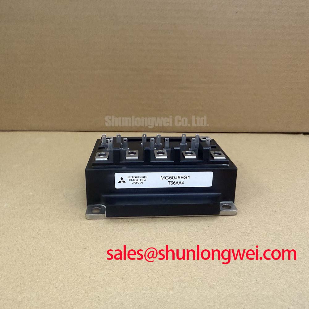
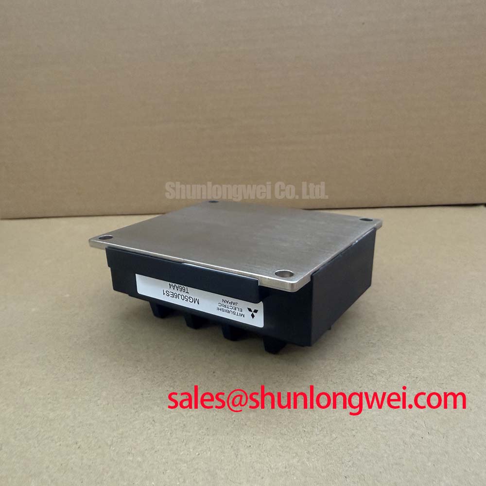
MG50J6ES1 Toshiba 600V 50A Dual IGBT Module for High-Frequency Motor Drives
Solving Switching Loss in Compact 600V Inverter Stages
How do engineers reduce switching losses in a 600V industrial inverter without exceeding the thermal budget of a compact enclosure? The Toshiba MG50J6ES1 answers this with a fifth-generation planar-gate IGBT chipset in a 2-in-1 half-bridge package. Rated at VCES = 600V and IC = 50A, it pairs fast turn-off behavior with a co-packaged free-wheeling diode optimized for PWM operation. Key benefits: low VCE(sat), short tail current. Best fit: 5–15 kW three-phase variable-speed drives prioritizing efficiency and footprint.
Frequently Asked Engineering Questions
Front-Loaded Answers for Designers Evaluating the MG50J6ES1
What is the configuration of the MG50J6ES1? It is a 2-in-1 (half-bridge) IGBT module integrating two N-channel IGBTs and two anti-parallel FWDs, simplifying three-phase bridge layouts by reducing module count.
Why is the 600V rating a deliberate choice over 1200V parts? A 600V class device offers lower VCE(sat) and softer switching for 400V-class DC bus systems, directly improving conduction and switching efficiency in this voltage range.
How does the integrated FWD affect inverter performance? The matched FWD minimizes reverse-recovery charge, lowering diode-induced turn-on loss in the opposing IGBT during commutation in inductive loads.
Is the MG50J6ES1 suitable for paralleling to scale current? Paralleling requires careful gate-loop matching and balanced thermal paths; designers should consult the official application notes and validate dynamic current sharing on a prototype before production.
Key Parameter Overview
Critical Specifications Highlighted for Rapid Design Validation
| Parameter | Value | Engineering Significance |
|---|---|---|
| Manufacturer | Toshiba | Established Japanese power semiconductor supplier |
| Configuration | 2-in-1 (Half-Bridge) | Reduces module count in three-phase inverters |
| VCES | 600 V | Suited for 400V AC line / 540V DC bus systems |
| IC (DC) | 50 A | Targets sub-15 kW drive stages |
| ICP (Pulsed) | 100 A | Headroom for motor startup transients |
| VCE(sat) | ~2.1 V typ. | Low conduction loss at rated current |
| VGES | ±20 V | Standard gate drive compatibility |
| Tj (max) | 150 °C | Thermal headroom for sustained PWM |
| Isolation Voltage | 2500 Vrms | Reinforced creepage for industrial mains |
| Integrated FWD | Yes | Optimized reverse recovery |
Technical Deep Dive
How Chip-Level Trade-offs Shape Switching Energy in the MG50J6ES1
The MG50J6ES1 belongs to Toshiba's J-series planar IGBT family, where the silicon recipe targets a deliberate balance between VCE(sat) and turn-off energy (Eoff). For 5–20 kHz carrier frequencies typical of general-purpose drives, this balance favors lower total loss compared to ultra-fast NPT variants that minimize Eoff at the cost of higher conduction drop.
An analogy: think of switching loss like braking a car. A sportier brake (faster IGBT) stops quickly but wears faster (higher EMI, dv/dt stress); a balanced brake stops smoothly with longer pad life. The MG50J6ES1 sits in this balanced category, which is why it has remained relevant for pumps, fans, compressors, and welding control circuits where audible noise and EMI compliance with VFD standards matter as much as raw speed.
A second analogy applies to the integrated FWD: reverse recovery charge (Qrr) behaves like residual water in a closed valve—the less left behind, the cleaner the next switching cycle. Toshiba's matched diode reduces this Qrr, lowering turn-on dissipation in the complementary IGBT during inductive commutation. Engineers exploring deeper trade-offs can consult our guide on decoding IGBT datasheets and the broader principles of switching loss minimization.
Application Scenarios & Value
Where the 600V / 50A Half-Bridge Earns Its Place in the BOM
Engineers often face a recurring dilemma: a three-phase 400V AC drive needs to handle a 30 A RMS motor current with margin for startup surge, but the cabinet allows only a modest heatsink. Using six discrete IGBTs increases interconnect inductance and assembly cost. The MG50J6ES1 resolves this by integrating two switches and two FWDs into one isolated package, shrinking the bus-bar loop and simplifying the gate-drive PCB.
Typical deployment areas include:
- Three-phase motor drives (pumps, fans, conveyors) at 5–11 kW
- Servo amplifiers with PFC front-end stages
- Welding inverter bridge legs requiring rugged short-circuit tolerance
- Small UPS output stages where IEC 62040 efficiency targets apply
- Induction heating drivers operating below 25 kHz
For designs needing higher current handling within the same J-series family, the related MG75J6ES50 offers a 75A rating in a similar half-bridge configuration. For newer-generation requirements at higher power density, the MG100J7CSAOA extends the platform with updated chip technology. Selection should be governed by validated thermal simulation rather than nameplate values alone—see our reference on IGBT thermal management.
From a strategic standpoint, the MG50J6ES1 remains a pragmatic choice for OEMs maintaining long-lifecycle industrial platforms where requalification cost outweighs the marginal efficiency gain of newer trench-gate alternatives. Its established footprint, predictable behavior, and compatibility with standard ±15 V gate drivers continue to make it a defensible BOM line for retrofit and replacement programs serving the global industrial automation base.