


Content last revised on September 20, 2026
CVM75BB160 Thermal-Electrical Evaluation: Reverse-Recovery Behavior and Practical Verification
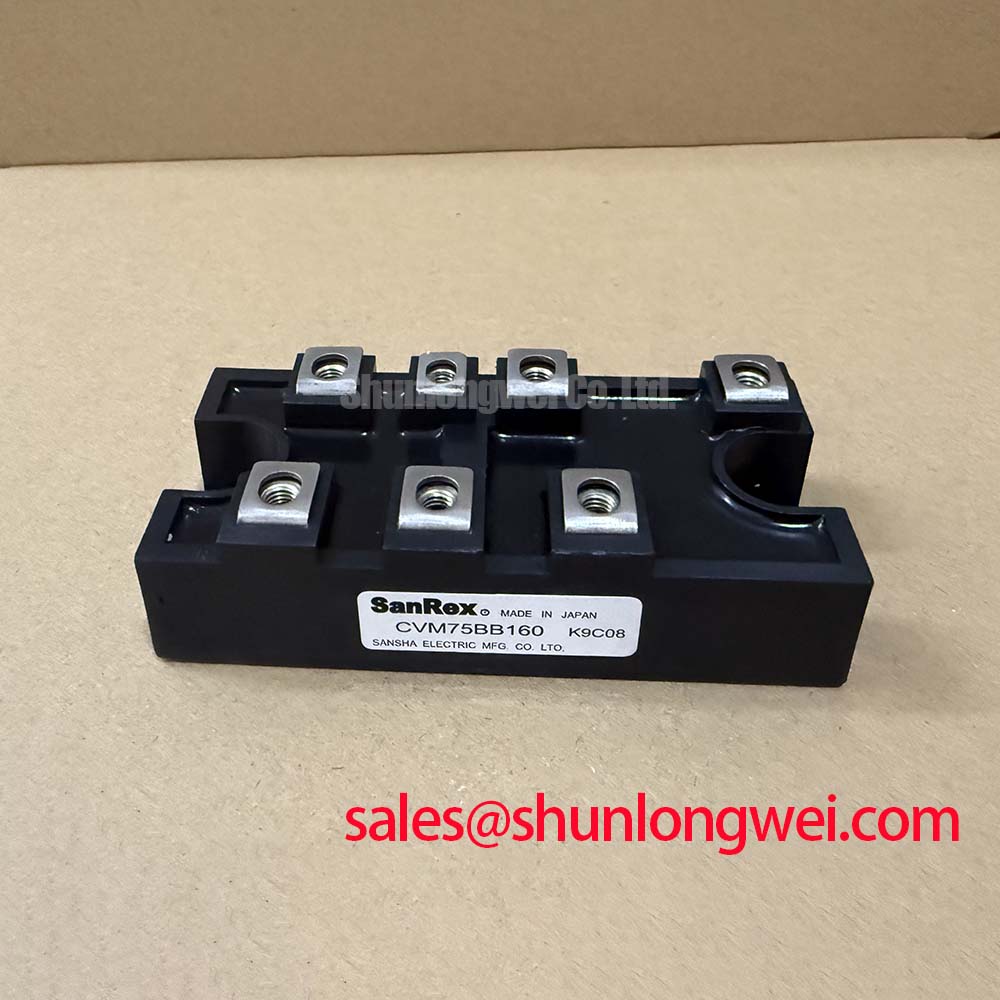
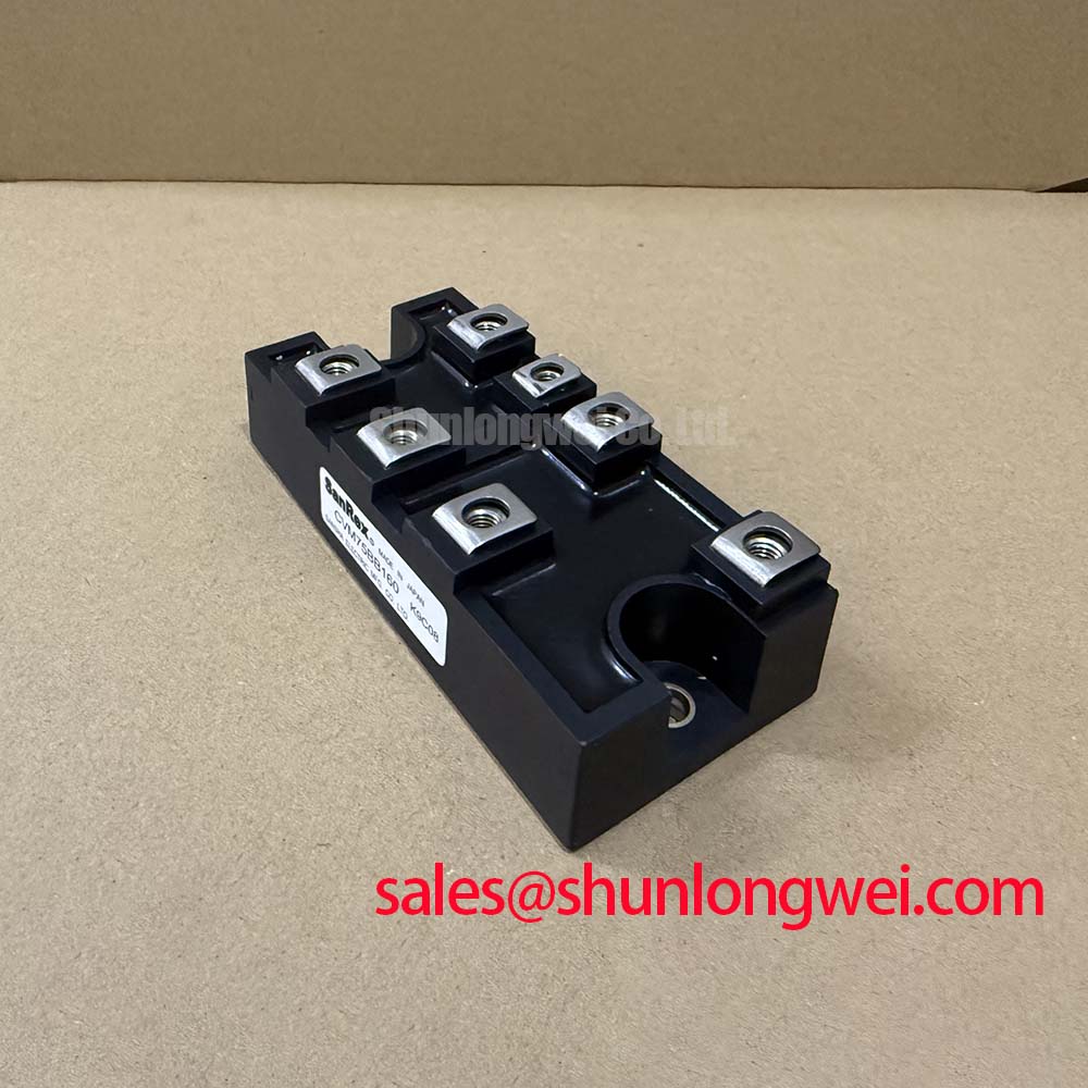
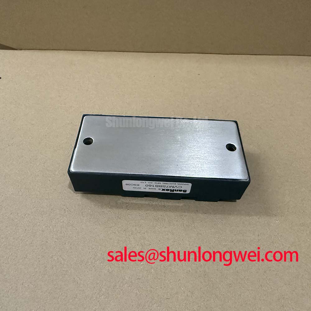
Before connecting the module to a power circuit, compare the case marking with the equipment bill of materials, inspect the terminal area for mechanical damage, and verify the cold-state diode paths with a multimeter in diode-test mode using the original circuit documentation as the terminal reference. The CVM75BB160 is a SanRex thyristor and diode module with an official repetitive peak reverse-voltage rating of 1600 V for both diode and thyristor elements.
Its official DC output-current rating is 75 A at a case temperature of 98 degrees C. This rating is meaningful only when the actual assembly can hold the case temperature within the specified operating condition. A service inspection should therefore include heatsink flatness, thermal interface condition, terminal tightness, cooling-path cleanliness, and the measured temperature behavior of the existing installation.
The available official specifications identify a maximum forward voltage of 1.50 V at 75 A, but do not establish a numeric reverse-recovery charge, reverse-recovery peak current, soft-recovery classification, or reverse-recovery time for this product page. These values should not be inferred from another module family. When a commutation waveform needs investigation, the service engineer should measure the actual current and voltage transitions in the host circuit, using suitable isolated instrumentation and a known-good channel where available.
Design Consideration: reverse-recovery behavior can affect commutation loss, voltage overshoot, and conducted or radiated noise in phase-controlled and resonant power assemblies. The relevant behavior is determined by the circuit inductance, commutation path, load condition, snubber network, temperature, and the installed module characteristics. System engineers should validate peak voltage and current against the 1600 V blocking boundary during representative switching tests rather than treating a general recovery characteristic as a guaranteed module-specific value.
For medium-frequency induction melting and hardening furnace power supplies, this module can be evaluated where the original electrical topology, thermal arrangement, and terminal arrangement match the equipment design. A related power-semiconductor unit, PK55FG120, can be reviewed separately when tracing an associated front-end or auxiliary power stage; it should not be treated as an automatic substitute for the CVM75BB160.
Bench Tip: Isolate stored energy, use ESD-controlled handling, and record each cold-state diode reading before comparing it with a known-good module or the original service documentation.
| Official Specification | CVM75BB160 Value | Verification Relevance |
|---|---|---|
| Repetitive peak reverse voltage | 1600 V | Confirm that measured circuit stress remains within the rated blocking boundary. |
| DC output current | 75 A at Tc = 98 degrees C | Assess together with actual case-temperature control. |
| Forward voltage | 1.50 V maximum at 75 A | Use only under the stated official test condition. |
| Operating junction temperature | Minus 30 to plus 150 degrees C | Review with the complete thermal path and measured operating load. |
CVM75BB160 Operational Boundaries: Evaluating Non-Repetitive Surge On-State Current Limits
The official surge forward-current rating for the CVM75BB160 is 1000 A. This is a non-repetitive surge capability, not a continuous current rating and not a basis for repeated fault operation. A maintenance record should distinguish a one-time abnormal event from normal operating current, because repeated surges can change the thermal and electrical condition of the surrounding assembly even when a module remains electrically functional during a basic static test.
The supplied product data does not state a sinusoidal 10 ms half-cycle surge current value, a thyristor on-state surge rating identified as ITSM, or a module-specific fuse I2t withstand figure. Those values must be obtained from the applicable official datasheet or the original equipment protection documentation before selecting or validating semiconductor fuse coordination. The 1000 A surge forward-current specification should not be relabeled as an ITSM value or used to derive an unsupported fuse limit.
Engineering Recommendation: after an overcurrent trip or suspected short circuit, isolate the assembly and inspect the complete current path before reapplying reverse voltage. Verify line-side and load-side insulation, busbar condition, fuse status, cooling performance, and the module’s static terminal behavior against the circuit schematic. A diode reading that differs from a comparable known-good channel may warrant further investigation, but a multimeter result alone does not establish dynamic switching performance or junction condition.
The official isolation specification is 2500 V AC for one minute. It defines a rated dielectric-test condition, not a general instruction to apply that voltage during field troubleshooting. Field dielectric testing must follow the equipment manufacturer’s approved procedure, including disconnected sensitive circuitry and the correct test points. The SanRex product family context is available through SanRex power semiconductor modules; final terminal and test conditions must still be verified for this exact installed assembly.
For repair assessment, compare physical fit, terminal mapping, voltage class, current rating at the stated case temperature, isolation requirement, and cooling interface. The FRS200CA100 is a separate related device that can be reviewed during a parts comparison, but compatibility must be established from the original circuit function, mechanical drawing, and validated electrical requirements.
Benchtop Waveform Tuning: Mitigating Stress via I2t Sub-Cycle Melting Rating on CVM75BB160
Start fault-protection evaluation by identifying the fuse part number, its time-current characteristic, its clearing I2t data, and the exact semiconductor branch it protects. The CVM75BB160 official data provided here specifies 1600 V reverse-voltage capability, 75 A at Tc = 98 degrees C, and 1000 A surge forward current. It does not provide a semiconductor fuse coordination table, a module-specific I2t limit, or a guaranteed fault-clearing energy value.
Design Consideration: fuse coordination requires comparing the fuse pre-arcing and total-clearing behavior with the device and circuit withstand characteristics under the actual prospective fault current. That work must use the fuse manufacturer’s documentation, the original equipment protection design, and applicable module data. It is not defensible to claim that any particular fuse will prevent package damage, nor to promise zero damage under a dead-short event, without a complete, validated protection study.
In a benchtop investigation, observe whether the protection chain responds consistently across equivalent channels. Check the fuse seating, connection resistance, busbar joint condition, trigger circuitry, current-sensor wiring, and interlock sequence. If a waveform has abnormal ringing or a delayed interruption, the result may indicate a problem in the surrounding commutation path, sensing circuit, or protection timing. Compare with a known-good signal path using appropriate voltage and current probes rather than assigning a single cause from one symptom.
Where a phase-controlled furnace power supply is being repaired, confirm the commanded firing sequence and the measured device terminal polarity before energizing at reduced system risk. The module rating does not define gate-drive voltage, gate current, trigger-current requirements, or allowable gate-circuit impedance. The system integrator should verify these requirements from the original equipment documentation and the exact CVM75BB160 datasheet.
Protection coordination also depends on the DC-link or line configuration, transformer leakage behavior, wiring inductance, load condition, and any snubber components. Minimize parasitic current-loop inductance where the existing design allows it, particularly to reduce inductive overshoot during interruption, then verify measured peak conditions against the system voltage boundary. Practical integration guidance for power-stage layout, thermal management, and test discipline is available in IGBT Design & Integration; its general principles must be adapted to the thyristor and diode topology actually present.
Transient Dynamics & Electrical Design: Mechanical Mounting Torque Sequence and Thermal Resistance on CVM75BB160
Clean the heatsink contact area, inspect it for burrs or contamination, and place the CVM75BB160 squarely on the mounting surface before tightening the hardware. The official junction-to-case thermal resistance is 0.23 degrees C/W. This value describes the thermal path from junction to case under the manufacturer’s defined conditions; it does not include the thermal interface material, heatsink, airflow, coolant circuit, enclosure temperature, or mounting quality.
A uniform thermal interface is essential when evaluating the stated 75 A at Tc = 98 degrees C rating. Design Consideration: apply the thermal interface material according to the equipment manufacturer’s process, use the prescribed mounting hardware, and tighten mounting points progressively in the documented sequence so the baseplate is not distorted. The required torque is system and hardware dependent unless it is explicitly stated in the exact module documentation, so it should not be assumed from a generic package practice.
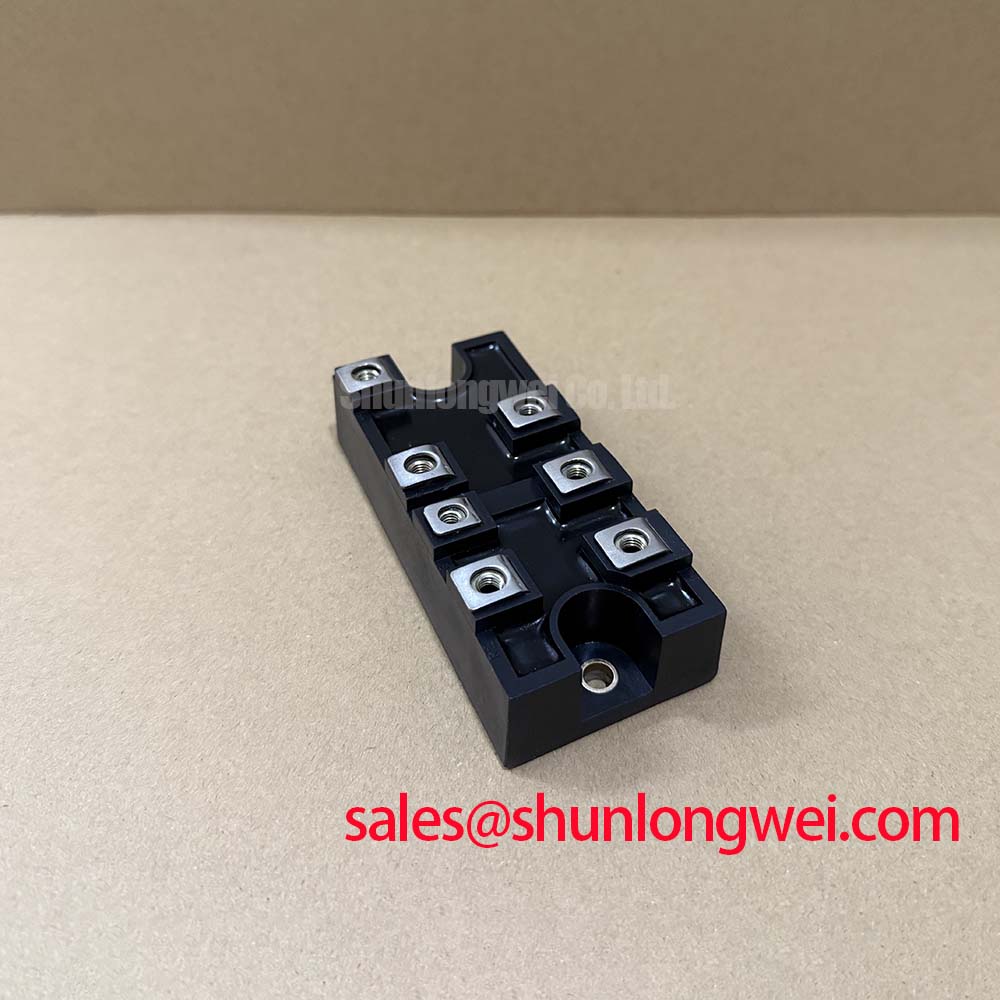
After mounting, inspect conductor alignment before tightening power terminals. Avoid forcing busbars or cables into position through the module terminals, because mechanical preload can alter contact pressure and transmit stress into the package. Confirm the terminal arrangement from the module drawing and schematic; the supplied specifications do not authorize a terminal map, gate connection, polarity orientation, or mounting-hole dimension to be reproduced here.
The permitted operating junction-temperature range is minus 30 to plus 150 degrees C. During service evaluation, temperature measurements should be taken at repeatable locations and interpreted alongside load current, cooling condition, duty cycle, and ambient conditions. A case-temperature measurement is useful for trend comparison, but it is not a direct junction-temperature measurement. Engineers should establish the junction-temperature margin through the complete thermal model and measured operating behavior of the equipment.
The 2500 V AC for one minute isolation rating supports the required dielectric boundary when the module is installed correctly, but the finished system still depends on heatsink grounding, creepage and clearance in the equipment, cable routing, enclosure condition, and the relevant system safety requirements. For induction heating equipment, verify that the power-stage layout, cooling system, interlocks, and protective functions are restored to the original validated configuration before returning the unit to service.