
Content last revised on September 19, 2026
Field Diagnostics and Commissioning for DAC2F150N4 Rectifier Connections
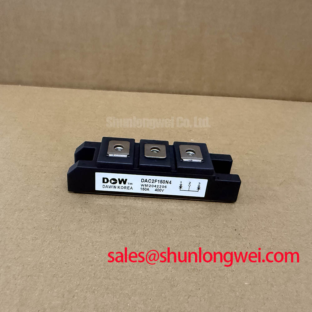
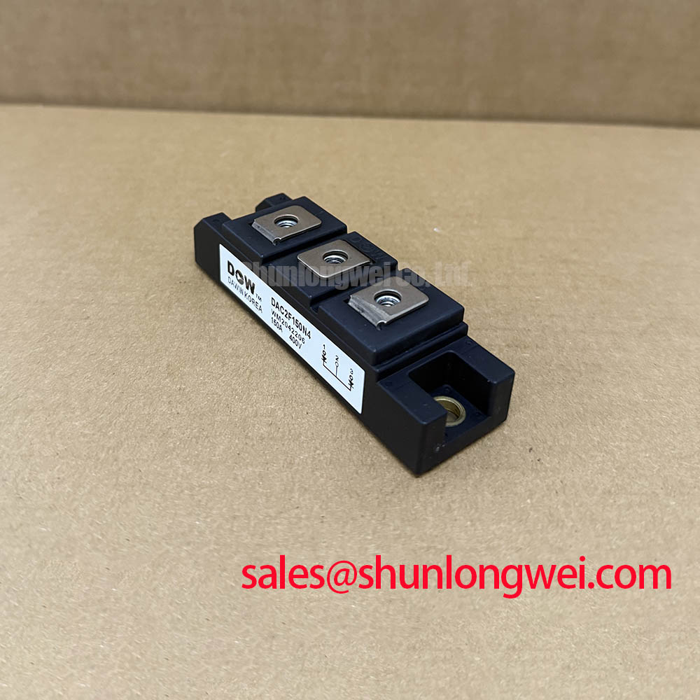
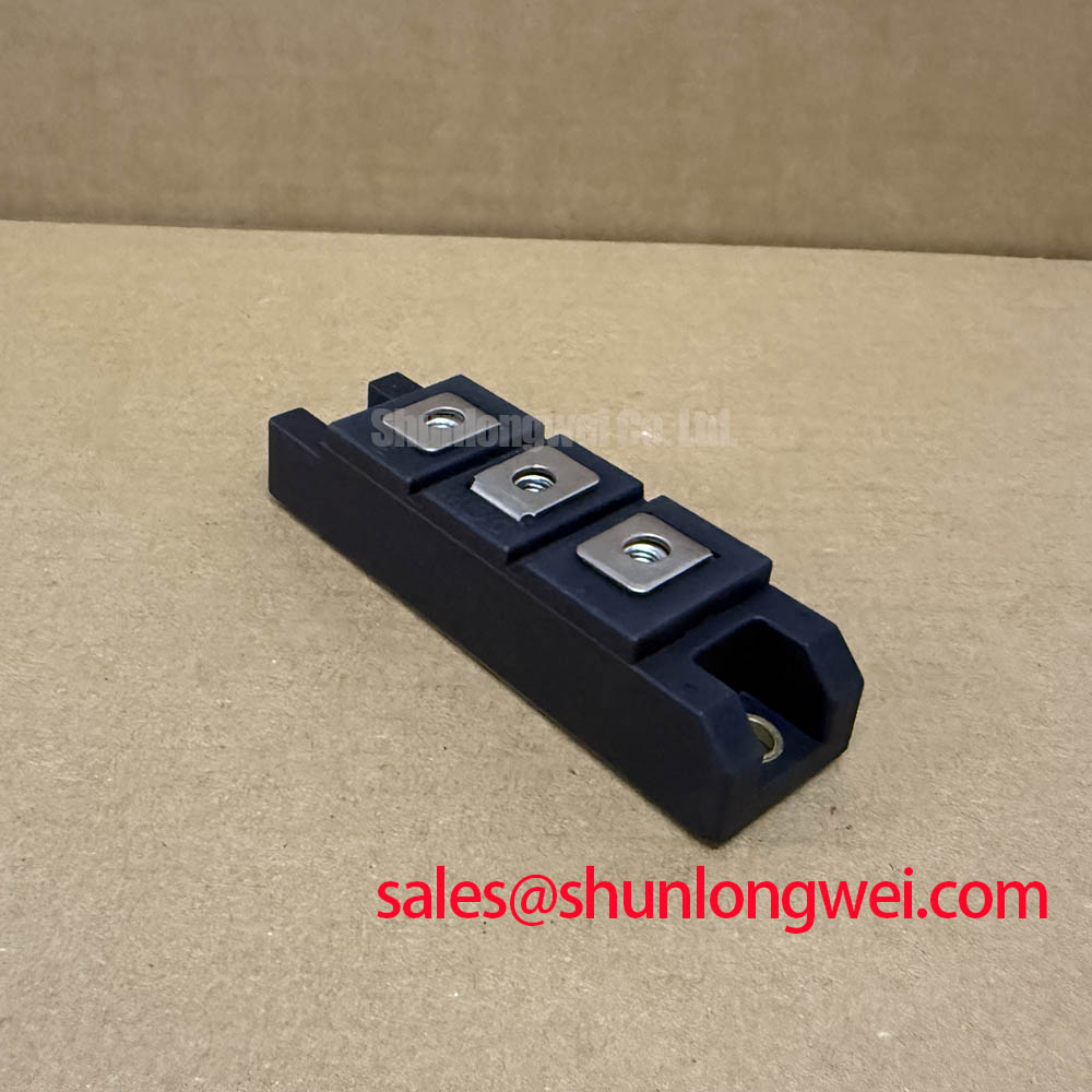
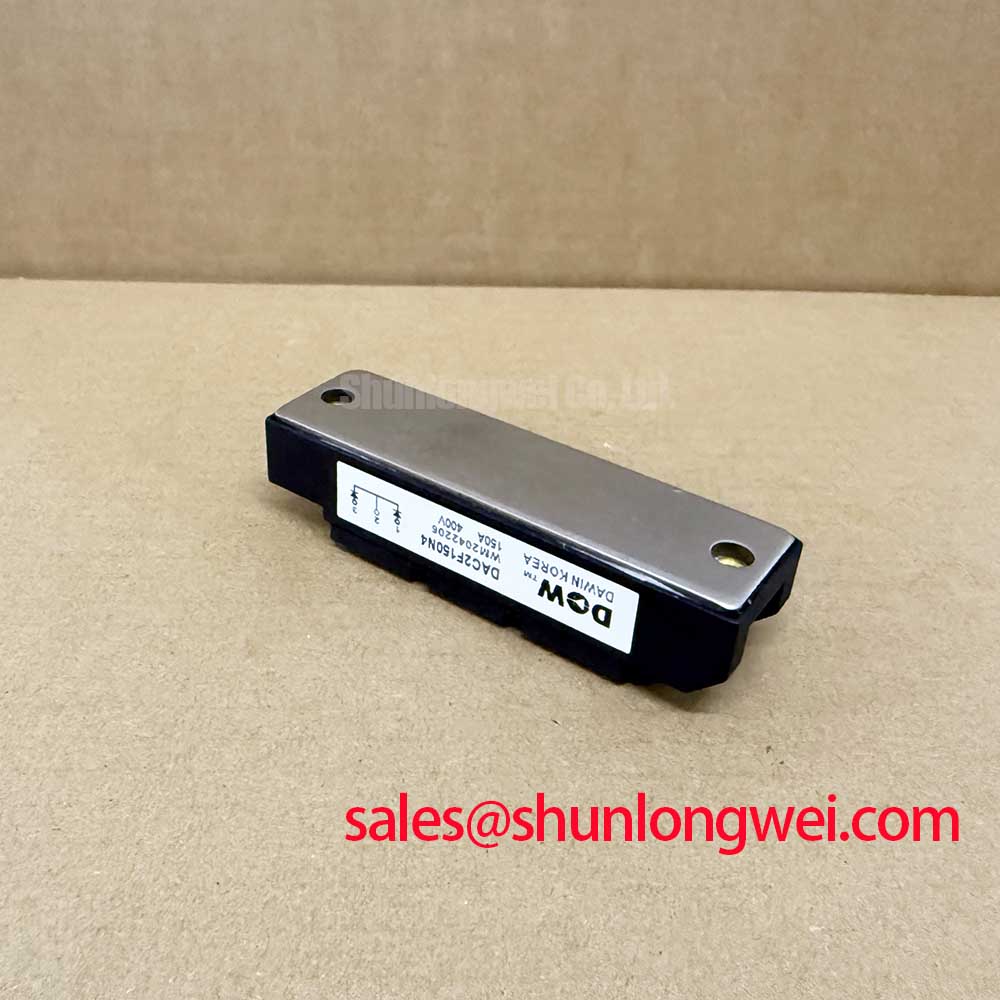
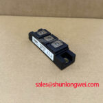
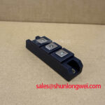
For a stopped heavy duty variable frequency AC motor drive, identify the DAC2F150N4 as the AC to DC rectification stage before evaluating any inverter side fault. The module’s three phase full wave rating means its terminals are part of the incoming AC supply path and the DC bus charging path. Terminal designations and physical orientation must be verified against the original equipment documentation and the module marking before any meter test or cable reconnection.
A diode test can provide a useful initial screen only after the DC link has been proven discharged and external parallel paths have been considered. Measure each phase terminal toward the DC positive and DC negative terminals in both polarities. Comparable directional conduction behavior across the three phase paths supports further investigation, while an unexpected low resistance path, open path, or substantial imbalance should be checked again with connected cables removed where the service procedure permits. Snubbers, precharge circuits, contactors, bus capacitors, and control electronics can otherwise influence readings.
The specified forward voltage drop is 1.35 V at Tj 25°C and I F 150 A. This is an official test condition, not a field acceptance threshold for a handheld meter. A meter applies a much lower test current, and its displayed value cannot be used to reproduce the datasheet condition. When a drive presents DC bus ripple, charging difficulty, abnormal AC input current, or a repeated input protection trip, evaluate line supply symmetry, upstream fuses, contactor condition, precharge operation, DC bus capacitors, and the module’s diode paths together.
DAC2F150N4 does not have an auxiliary emitter or Kelvin emitter terminal. In a drive inverter, Kelvin emitter routing is associated with certain controlled switching devices and their gate drive return paths, not with this uncontrolled three phase rectifier. Keeping that distinction clear avoids commissioning a rectifier module with inverter gate drive assumptions.
Where the same cabinet includes an inverter power stage, the topology may also contain a device such as 6MBI300U-120. That is a separate controlled power module class and must be assessed by its own terminal map, electrical ratings, driver interface, cooling arrangement, and original circuit function. It is not evidence that the DAC2F150N4 rectifier can be substituted by an IGBT module.
Assembly Integrity and Layout Architecture Around the AC to DC Rectifier Stage
Before energisation, verify that the module body seats flat against the assigned cooling surface and that busbars reach the terminals without applying side load. The official mounting torque for the M6 main terminals is 5 ± 1 N·m. This value applies to the main terminal connection and should not be extended to mounting hardware unless the original mechanical documentation states it.
⚠️ Field Alert: Tighten M6 main terminals to the specified 5 ± 1 N·m only after the busbar is fully aligned, because forcing a misaligned conductor can damage threads or leave a high resistance joint.
Design Consideration: keep the three AC phase conductors and the positive and negative DC bus conductors mechanically supported, electrically clear, and arranged to minimise unnecessary loop area. This supports predictable commutation behavior and reduces the chance that vibration or thermal movement transfers force into the module terminals. The actual clearance, creepage, busbar insulation, enclosure protection, and grounding requirements are determined by the equipment voltage, pollution environment, local regulations, and the complete drive construction.
No reinforced isolation voltage, common mode transient immunity rating, or insulation coordination value is provided in the stated official specifications for DAC2F150N4. Such claims should therefore not be assigned to this model. Engineers assessing an isolated control supply, gate driver barrier, encoder interface, or communication port should evaluate those separate assemblies from their applicable documentation. For motion systems using deterministic communication, the operating behavior of interfaces such as Sercos III real time communication is a system level issue; rectifier layout can be relevant to conducted noise, but the diode module does not independently establish communication or EMC compliance.
At switching frequencies used by a downstream inverter, the DAC2F150N4 itself remains an input rectifier. The inverter switching frequency can still affect cabinet heat, DC bus ripple spectrum, cable noise, and cooling demand across the drive. When integrating or repairing equipment, technicians should verify actual heatsink temperature, airflow condition, cabinet ambient temperature, fan operation, and measured line current under the intended load rather than applying a frequency based current derating figure that is not specified for this module.
DAC2F150N4 Operational Boundaries and Heat Sink Verification
The relevant official thermal boundary is the operating junction temperature range of -40°C to 150°C. The provided data does not include thermal resistance, transient thermal impedance curves, thermal capacitance values, case temperature limits, or a multi RC thermal model. A peak junction temperature calculation cannot be made responsibly from the listed ratings alone.
Engineering Calculation requires a documented loss model and validated thermal path data. Rectifier loss depends on the instantaneous current waveform, conduction interval, diode forward characteristics at operating temperature, AC supply condition, thermal interface, heatsink performance, and surrounding airflow. Although the listed 1.35 V forward drop establishes a reference at 150 A and 25°C junction temperature, it is not sufficient to predict operating loss over a loaded motor drive duty cycle.
During field recovery, inspect the thermal interface for incomplete contact, contamination, hardened compound, or uneven clamp pressure according to the original equipment assembly procedure. Check whether the cooling fan starts correctly, whether airflow passages are obstructed, and whether adjacent power devices are adding heat into the same heatsink. Infrared inspection can assist comparison between similar phases or modules, provided surface emissivity and access limitations are understood. A local hot region may indicate a connection, cooling, current sharing, or surrounding circuit concern and should be investigated with electrical measurements.
The 3000 A peak forward surge current is specified for a non repetitive, one cycle, 50 Hz half sine event. It must not be treated as a continuous overload allowance or a repetitive motor starting capability. For short circuit coordination, the drive designer must assess the complete protection chain, including semiconductor fuse selection, line protection, DC link energy, contactor interruption behavior, cable impedance, and the equipment fault clearing strategy. Fuse I²t coordination and fault energy withstand are system determined and require device curves and protection documentation that are not included in the listed DAC2F150N4 specifications.
For a repair evaluation, record the supply voltage, measured AC current balance, DC bus behavior, heatsink condition, and protection sequence before replacing a part. This preserves the evidence needed to distinguish a failed rectifier path from an upstream supply event or a downstream inverter fault that has stressed the input stage.
DAC2F150N4 Installation Conditions at Elevation and Electrical Transient Exposure
No official FIT rate, cosmic ray susceptibility, single event burnout rating, altitude rating, or DC bus derating curve is included in the provided DAC2F150N4 specifications. It would be inaccurate to calculate a failure in time rate, assign a neutron induced failure mechanism, or prescribe a voltage derating percentage for this rectifier module without qualified manufacturer data and the actual equipment operating conditions.
Design Consideration: at elevated installation sites, reduced air density can alter the cooling and insulation performance of the complete drive assembly. Engineers should verify enclosure thermal behavior, clearance and creepage requirements, input protection coordination, and maximum bus voltage using the drive manufacturer’s installation documentation and applicable standards. The final operating limits are determined by the system design, environmental classification, and test results, not by an unsupported assumption attached to the diode module.
Transient exposure should likewise be evaluated at system level. Incoming supply switching, transformer energisation, contactor operation, motor regeneration, DC bus wiring, and inverter commutation can each influence voltage stress and conducted noise. The 400 V V RRM value is the official repetitive peak reverse voltage rating and is the primary electrical identity to verify against the original rectifier position. Designers should capture representative line and DC bus waveforms under the intended operating states, then verify peak margins against the module rating and the equipment’s approved protection approach.
For broader reading on switching device efficiency and drive level integration, see Unlocking Efficiency in Industrial Drives. That technical material concerns IGBT technology and should be used as contextual information for the inverter stage, not as a specification source for the DAC2F150N4 diode rectifier.
If a repair review includes 3MBI50SX-120-02, confirm its circuit role independently. It is an IGBT module family reference and is not a direct replacement for DAC2F150N4, which has a three phase rectifier function. Original terminal function, voltage class, current duty, mechanical fit, thermal interface, and control architecture must all match before any replacement decision.