


Content last revised on March 8, 2026
EVG31-050 IGBT Module: Technical Data & Application Insights for Power Systems
Product Overview: Efficiency and Integration in a Single Package
Defining Performance in 600V Power Conversion Systems
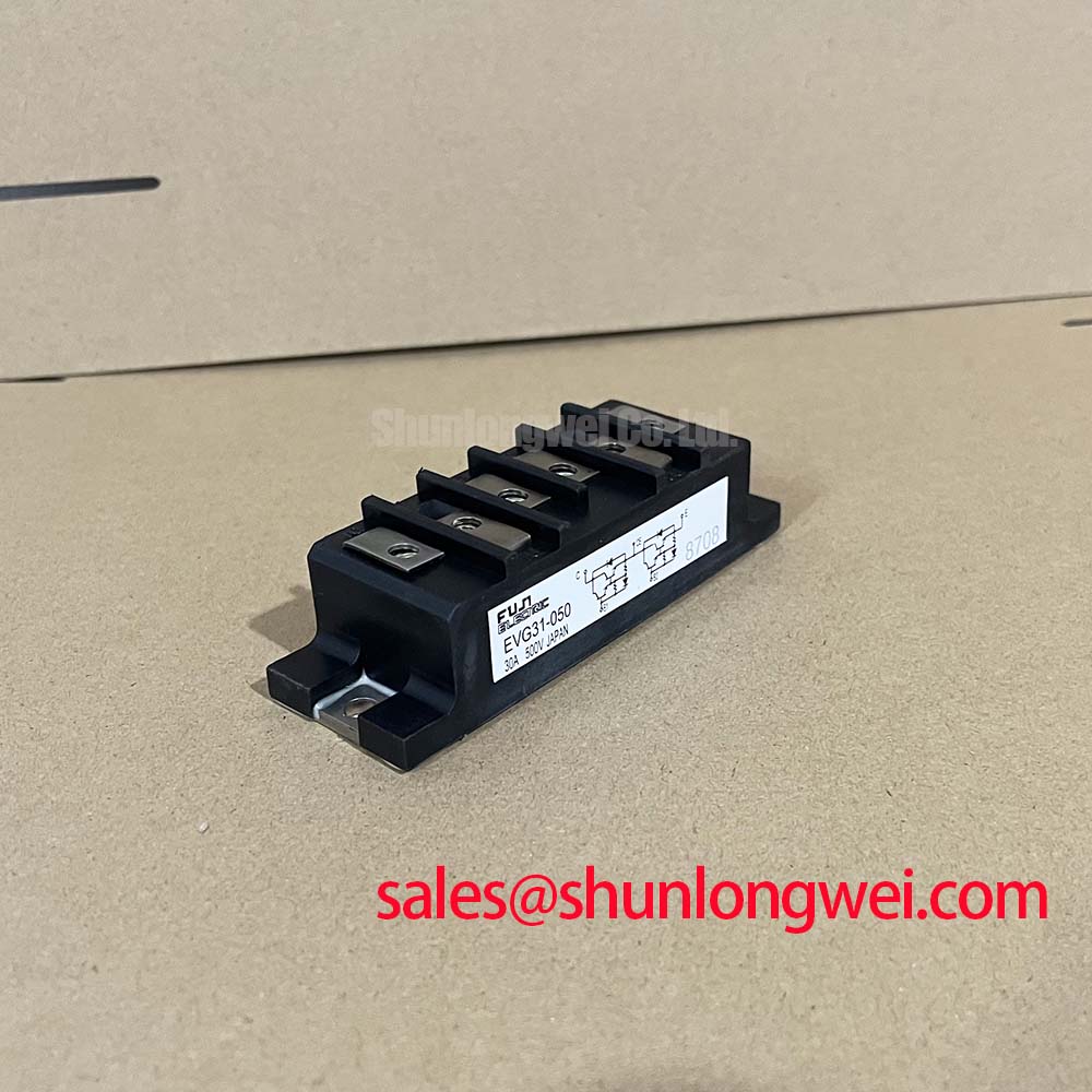
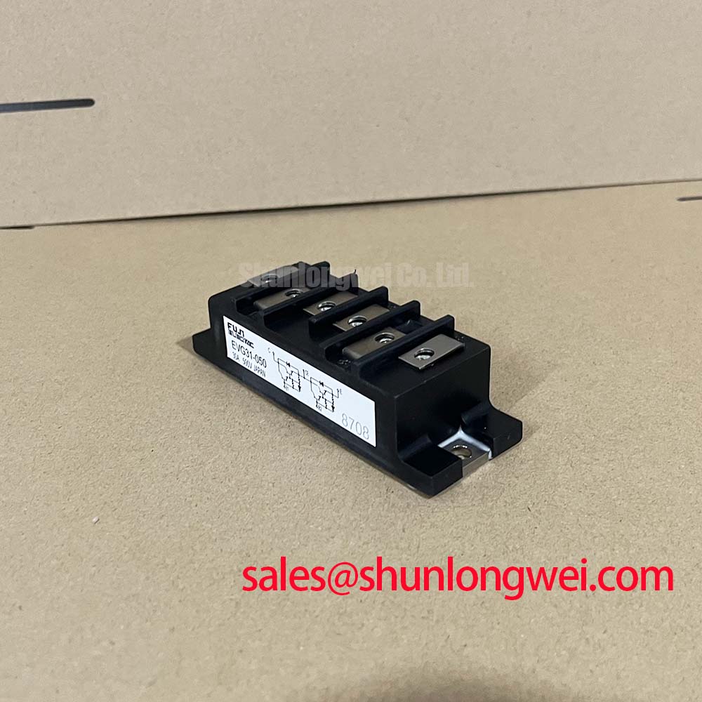
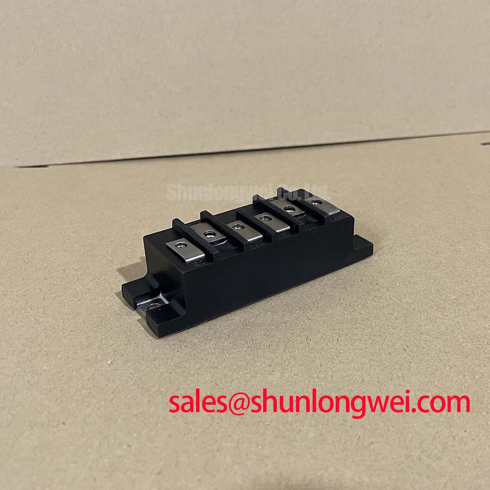
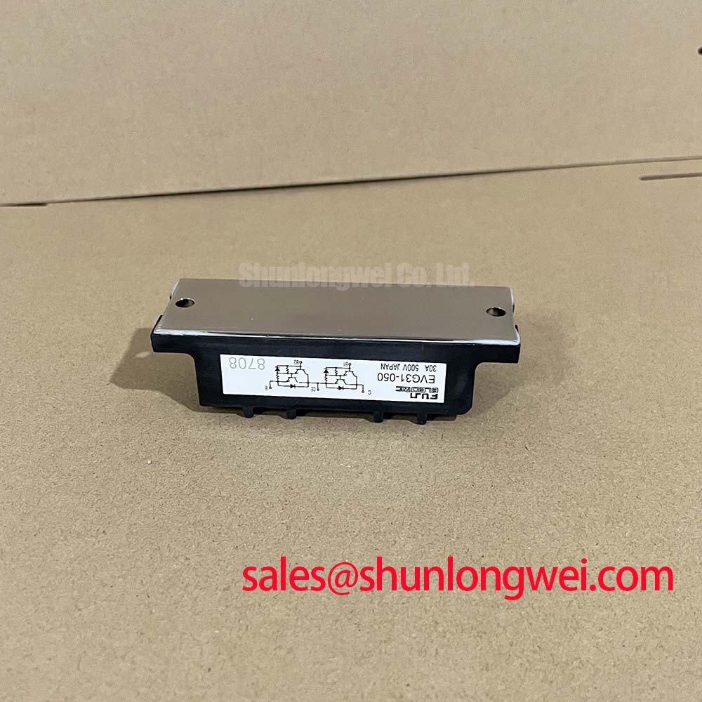
The EVG31-050 is a highly integrated 6-in-1 IGBT module engineered for superior efficiency in three-phase inverter applications. It combines a 600V collector-emitter voltage with a 50A continuous collector current and a low typical VCE(sat) of 2.2V. This specification profile is engineered for two primary engineering benefits: significantly reduced conduction losses and simplified thermal management. For designers working on compact motor drives or inverters, this module provides a robust power stage that directly addresses the challenge of balancing performance with system size and cost. For motor control systems requiring a balance of efficiency and power density, the EVG31-050 offers a strategically optimized solution.
Application Scenarios & Value
Achieving System-Level Benefits in Motor Drives and Inverters
The primary application for the EVG31-050 lies at the core of AC motor control systems, specifically within Variable Frequency Drives (VFDs) and servo drives. In a typical VFD design, minimizing heat dissipation within the enclosure is a critical challenge. The module's low collector-emitter saturation voltage (VCE(sat)) of 2.2V at its nominal current directly reduces conduction losses—a major source of waste heat. This is akin to reducing electrical friction; less energy is wasted as the switch operates, leading to higher overall inverter efficiency. The result is a lower thermal load on the heatsink, enabling designers to potentially specify a smaller, more cost-effective cooling solution or achieve greater power output within an existing thermal envelope. This characteristic is crucial for applications such as industrial automation, HVAC systems, and general-purpose inverters where reliability and energy efficiency are paramount.
This integrated six-pack configuration, which forms a complete three-phase inverter bridge, simplifies the power stage layout, reducing parasitic inductance and assembly complexity compared to discrete component solutions. For systems with similar power requirements but potentially different control interfaces or internal layouts, the related EVM31-050A may offer an alternative package or feature set to consider.
Key Parameter Overview
Decoding the Specs for High-Efficiency Inverter Design
The technical specifications of the EVG31-050 are tailored for robust performance in demanding power switching environments. The parameters below highlight the module's capabilities in voltage handling, current capacity, and thermal efficiency, which are critical inputs for any successful inverter design.
| Parameter | Symbol | Value | Conditions |
|---|---|---|---|
| Collector-Emitter Voltage | Vces | 600V | Tj = 25°C |
| Gate-Emitter Voltage | Vges | ±20V | |
| Continuous Collector Current | Ic | 50A | Tc = 80°C |
| Peak Collector Current | Icp | 100A | 1ms pulse |
| Collector-Emitter Saturation Voltage | VCE(sat) | Typ. 2.2V (Max. 2.7V) | Ic = 50A, Vge = 15V, Tj = 25°C |
| Total Power Dissipation | Pc | 230W | Per IGBT, Tc = 25°C |
| Operating Junction Temperature | Tj | -40 to +150°C | |
| Isolation Voltage | Viso | 2500V | AC, 1 minute |
Note: The parameters listed above are for reference. For complete electrical characteristics, thermal information, and performance curves, please refer to the official component documentation.
Technical Deep Dive
Analyzing Conduction and Switching Losses for Optimal Performance
A granular analysis of the EVG31-050's loss characteristics reveals its suitability for systems where efficiency is a key performance indicator. The two primary contributors to energy loss in an IGBT are conduction loss (when the switch is on) and switching loss (during the on/off transitions). The module's VCE(sat) of 2.2V provides a solid foundation for low conduction losses. The engineering value here is direct: for every amp of current flowing through the device, the power lost as heat is minimized, a critical factor in high-duty-cycle applications.
Equally important are the switching characteristics, which dictate performance as the Pulse Width Modulation (PWM) frequency increases. The datasheet specifies typical turn-on (ton) and turn-off (toff) times, which together determine the total switching energy (Ets). Think of switching energy as a small, fixed "energy tax" paid every time the IGBT turns on or off. At higher switching frequencies, this tax is paid more often, and total switching losses can become dominant. The EVG31-050 is designed to keep this tax low, enabling designers to operate at moderately high frequencies to improve motor performance and reduce audible noise without incurring an excessive thermal penalty. This balance is fundamental to designing efficient and quiet VFDs.
Frequently Asked Questions (FAQ)
What is the main advantage of the EVG31-050's 6-in-1 configuration?
The primary advantage is system integration. It combines all six IGBTs and six freewheeling diodes required for a three-phase inverter into a single, thermally optimized package. This simplifies PCB layout, reduces manufacturing complexity, and minimizes stray inductance between switches, which can improve electrical performance and reliability.
How does the VCE(sat) of 2.2V impact thermal design?
A lower VCE(sat) directly translates to lower power dissipation during the on-state (P_cond = VCE(sat) * Ic). This reduction in generated heat means a smaller, lighter, or lower-cost heatsink can be used to maintain the junction temperature within safe operating limits, directly impacting the overall power density and cost of the final system.
Is the EVG31-050 suitable for high-frequency switching applications?
The module is optimized for a balance between conduction and switching losses, making it well-suited for typical motor drive frequencies ranging from a few kHz up to around 15 kHz. While it can operate at higher frequencies, designers must carefully analyze the resulting increase in switching losses and ensure the thermal management system can adequately dissipate the additional heat.
What does the 2500V isolation rating signify for system safety?
The 2500V isolation voltage (Viso) ensures robust electrical insulation between the live power terminals and the module's baseplate, which is typically mounted to a grounded heatsink. This high isolation barrier is critical for meeting safety standards like IEC 61800-5-1 in industrial equipment, protecting both operators and downstream control electronics from high voltage potentials.
Strategic Design Considerations
Leveraging Integrated Power Modules for Future-Ready Systems
Integrating a module like the EVG31-050 is a strategic decision that extends beyond immediate performance gains. By leveraging a pre-packaged, tested, and optimized power stage, engineering teams can significantly shorten their design and validation cycles. This approach allows for greater focus on value-added areas such as control algorithms, user interfaces, and system connectivity. As industrial applications demand increasing power density and greater energy efficiency to meet evolving standards, the use of highly reliable and efficient integrated modules like the EVG31-050 becomes a critical enabler for developing competitive and robust power conversion systems.