Content last revised on October 24, 2026
7MBP150RA120 Replacement and Inspection Checklist
- Isolate the DC link, verify discharge with a suitable meter, and compare cold-state power-terminal measurements with the equipment service procedure.
- Inspect the module mounting surface and heatsink for contamination, damaged threads, uneven contact marks, and displaced thermal compound.
- Check the drive-board connector assignment, isolated control supplies, fault-return wiring, and input-signal reference before reconnecting the module.
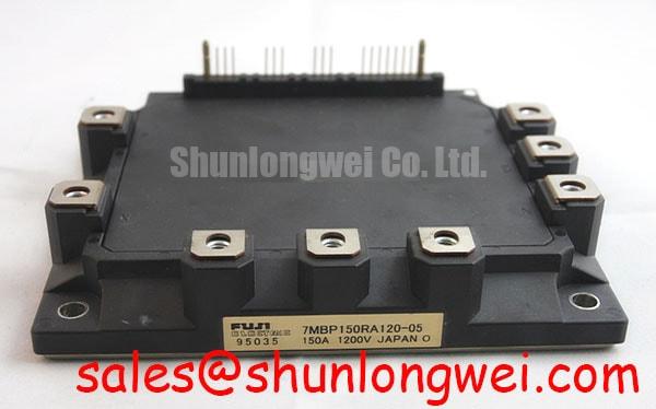
- Match the complete 7MBP150RA120 designation to the equipment bill of materials and check electrical, mechanical, and protection-interface compatibility.
The Fuji Electric 7MBP150RA120 is a 1200 V, 150 A intelligent power module for evaluation within compatible power-conversion assemblies. For a heavy-duty variable frequency AC motor drive repair, the useful starting point is the relationship between its inverter stage, braking branch, cooling interface, and existing controller. Matching voltage and current ratings alone does not establish replacement compatibility.
| Parameter | Value | Specification context |
|---|---|---|
| Collector-emitter voltage | 1200 V | Official Specification: VCES; a device blocking rating. |
| Collector current | 150 A | Official Specification: IC; applicable operating conditions govern usable current. |
| Collector-emitter saturation voltage | 2.2 V typical at 150 A | Official Specification: typical VCE(sat), not a maximum loss guarantee. |
| Brake-chopper collector current | 50 A | Official Specification: braking-switch current rating. |
| Diode forward voltage | 1.8 V typical at 50 A | Official Specification: the applicable diode branch and test conditions must accompany loss calculations. |
| Inverter junction-to-case thermal resistance | 0.12 °C/W per IGBT | Official Specification: excludes the thermal interface and heatsink. |
| Protection and integration details | Consult Datasheet | Temperature threshold and sensing location, short-circuit timing, control supply, pin assignment, mounting torque, and transient thermal curves. |
Preventing Spurious Faults: Eliminating Thermal Grease Pump-Out Guidelines for 7MBP150RA120
Inspect the heatsink contact pattern before removing the remaining thermal compound, because displaced material can reveal uneven pressure or local separation. Design Consideration: grease pump-out is one possible contributor to increasing interface resistance during temperature cycling; an intermittent thermal fault also warrants examination of cooling airflow, sensor wiring, loading, and protection signals.
Check module-baseplate contour and heatsink flatness against the permitted mounting geometry rather than assuming that visible convexity requires correction. Do not grind or straighten the module baseplate. Remove raised debris from the mating surface without changing its specified finish, and examine the mounting holes for conditions that could prevent the fasteners from producing consistent clamping force.
Engineering Recommendation: apply the selected thermal-interface material using its qualified assembly method, then tighten progressively in a diagonal sequence with a calibrated tool and the manufacturer-specified torque. Compound quantity and final bond-line thickness should follow the module and interface-material instructions. An arbitrary thickness target can leave incomplete coverage or excessive thermal resistance, especially when the mating surfaces have different permitted contours.
Maintain clearance around control connectors and power terminals so the wiring does not pull the assembly out of alignment. After reassembly, compare case-temperature trends and cooling conditions at repeatable operating points. A changed temperature rise is evidence for further investigation; it does not independently identify pump-out, semiconductor damage, or an incorrect protection threshold.
Benchtop Waveform Tuning: Mitigating Stress via Coordination of High-Speed Arcing Voltage on 7MBP150RA120
Compare the proposed semiconductor fuse’s total clearing behavior and arcing voltage with the actual DC fault circuit before approving protection coordination. Design Consideration: fuse performance depends on applied voltage, prospective fault current, circuit inductance, and the manufacturer’s test conditions. Pre-arcing data alone do not describe the energy admitted through the complete interruption event.
The module’s electronic short-circuit response and the upstream fuse perform different tasks. Electronic detection must initiate shutdown within the applicable short-circuit safe operating area, while the fuse addresses fault interruption within its rated application. Treat a fuse I2t comparison as one part of coordination; it cannot by itself establish that an IGBT survives a fault or that an enclosure contains every failure mode.
For desaturation-based protection, distinguish the normal 2.2 V typical VCE(sat) reference from the protection system’s detection threshold. Engineering Recommendation: review sensing delay, switching-transient rejection, fault propagation, and controlled shutdown together. Excessive delay increases semiconductor stress, while overly abrupt fault turn-off can increase collector-emitter overshoot. Use the module’s intended protection interface when evaluating these interactions.
Capture DC-link voltage, collector-emitter voltage, current, and fault response with appropriately rated probes and a controlled test arrangement. Evaluate fuse arcing voltage separately from ordinary switching overshoot: the two events have different current paths and time histories. Destructive short-circuit validation belongs in a suitably contained qualification setup.
When evaluating carrier-frequency changes, account for switching losses alongside conduction losses and cooling capability. Higher ambient temperature, obstructed airflow, and heatsink contamination can reduce thermal headroom. Determine operating limits from the relevant loss characteristics and measured temperatures across the intended duty cycle rather than assigning a universal switching-frequency range to the 7MBP150RA120.
7MBP150RA120 Circuit Protection & Reliability: Evaluating Transient Thermal Behavior and Heatsink Performance
Use transient thermal impedance to assess a pulsed overload instead of applying steady-state thermal resistance to every event. The specified 0.12 °C/W per inverter IGBT describes the junction-to-case thermal path under its stated conditions; it does not include thermal compound, heatsink spreading, airflow, or neighboring devices heating the assembly.
Engineering Calculation: for a rectangular loss pulse under the applicable initial conditions, estimated junction-temperature rise follows ΔTj = Ploss × Zth(j-c)(t), using the manufacturer’s transient thermal impedance at the pulse duration. Repetitive loading requires the preceding thermal history. A multi-RC representation should reproduce the published response rather than use guessed time constants.
Separate inverter-switch losses from braking-branch losses when constructing the thermal assessment. The 50 A brake-chopper rating describes a different branch from the inverter’s 150 A rating. During deceleration, braking duty and resistor-system behavior influence thermal loading; physical proximity can also affect the case-temperature distribution.
Design Consideration: a temperature sensor reports the temperature associated with its location and response time. It should not be treated as an instantaneous junction thermometer. Correlate its signal with operating current, switching activity, case measurements, and the thermal model when investigating overload trips. Avoid converting an approximate protection-temperature reference into a guaranteed allowable operating junction temperature.
Changes to energy-flow direction or repetitive loading require a fresh thermal assessment. For example, evaluating a different bidirectional converter duty would require verification of topology, control compatibility, and temperature excursions rather than an assumed service-life improvement. The Resonant Topologies in Home Appliances guide provides topology context, but its resonant-circuit discussion does not establish this module’s ratings.
Material comparisons also need a clear boundary: the silicon carbide semiconductor physics reference and Wolfspeed SiC Schottky diode documentation describe a separate technology context. Their characteristics should not be transferred to the diode losses or protection limits of this Fuji Electric module.
Field Diagnostics & Commissioning: Gate-Drive Interface Checks When Replacing 7MBP150RA120
Establish whether the gate-drive resistance is accessible before planning resistor changes: an intelligent power module integrates drive functions, and its controller input is not an exposed IGBT gate. For the 7MBP150RA120, evaluate the designated control and fault interfaces rather than treating a logic-input resistor as an external gate resistor.
Engineering Recommendation: where an equipment redesign genuinely exposes separate turn-on and turn-off gate paths, tune them against measured switching energy, ringing, overshoot, and protection behavior. Increasing resistance can reduce switching speed while increasing switching loss; changing turn-off impedance also affects the response to Miller-coupled current. These relationships require validation in the actual circuit.
Practical tip: keep the commutation busbar paths compact and balanced, then verify turn-off voltage margin with an appropriately configured double-pulse test before accepting a layout change.
Inspect the control isolator’s common-mode transient immunity alongside its supply decoupling, return routing, and fault-channel behavior. Design Consideration: a switching-correlated logic disturbance may originate in several coupling paths. Compare signals on both sides of the isolation barrier and at the module input before assigning the problem to an optocoupler, digital isolator, or power stage.
For replacement evaluation, compare the 7MBR35SD120 by circuit configuration, ratings, mounting geometry, and interface requirements; its part-family relationship does not establish interchangeability. Likewise, the 7MBI100U4E-120 requires its own topology and drive assessment when considered elsewhere in a power-conversion assembly. Complete commissioning by checking phase-current balance, fault reporting, command timing, and temperature behavior through controlled load changes.