



Content last revised on September 10, 2026
2MBI75P-140 Thermal-Electrical Optimization: Thermal Time Constants and Peak Junction Practical Tuning
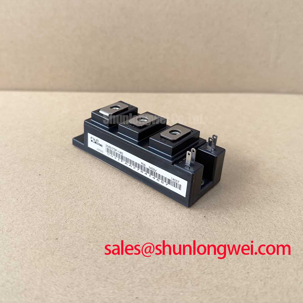
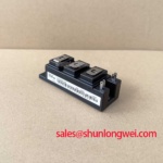
The Fuji Electric 2MBI75P-140 IGBT module is rated at VCES = 1400 V and IC = 75 A at TC = 80°C, according to the Official Datasheet Specification. Its 150 A collector current pulse rating applies to a 1 ms pulse condition and should not be treated as a continuous operating current allowance. The specified maximum power dissipation is 480 W, while the maximum specified junction temperature is +150°C.
For maintenance assessment, the junction-to-case thermal resistance is specified as 0.26°C/W for the IGBT and 0.48°C/W for the free-wheel diode. These values describe the semiconductor-to-case thermal path, not the complete thermal path through interface material, heatsink, airflow, enclosure temperature, and accumulated dust. A heavy-duty variable frequency AC motor drive can experience repeated acceleration, deceleration, and torque transient events that create thermal cycling even when the measured average output current appears moderate.
Design Consideration: transient thermal behaviour should be reviewed using the manufacturer’s applicable thermal impedance information and the actual load pulse profile. A simple steady-state calculation can underestimate junction excursion during intermittent overloads because the die, baseplate, thermal interface, and heatsink respond at different rates. During commissioning, technicians should log heatsink temperature, DC-link current, switching activity, and drive load profile together rather than treating any one measurement as a complete thermal diagnosis.
Keep the mounting face clean and flat, apply thermal interface material consistently, and inspect for dried, displaced, or contaminated compound during scheduled maintenance. Airflow restriction can elevate case temperature without changing the electrical control settings. ⚠️ Maintenance Note: Periodically monitor terminal contact temperature rise and confirm that heatsink fins and cooling-air paths remain clear before increasing drive duty.
The module’s VCE(sat) of 2.8 V typical and 3.4 V maximum at IC = 75 A is an Official Datasheet Specification. This parameter supports conduction-loss estimation at the stated test condition, but it must not be used alone to predict operating temperature because actual switching loss depends on the drive circuit, DC-link conditions, current waveform, and switching behaviour.
Transient Dynamics & Electrical Design: Symmetrical Busbar Geometry for High-Current 2MBI75P-140
When parallel operation is being evaluated, inspect busbar geometry before assuming that modules will share current evenly. The positive temperature coefficient behaviour of IGBT conduction voltage can assist static current sharing under appropriate operating conditions, but dynamic current sharing is governed by far more than conduction behaviour. Gate-loop impedance, common-emitter inductance, power-loop inductance, gate-driver propagation delay, individual thermal paths, and physical conductor symmetry all influence switching balance.
Engineering Recommendation: arrange parallel current paths with comparable conductor length, cross-section, and return-path geometry so that one module is not exposed to a materially different parasitic inductance than another. Place DC-link capacitors and power interconnections to minimize the commutation loop area, particularly where turn-off overshoot must be controlled. System engineers should verify peak collector-emitter voltage against the DC-link voltage during double-pulse or representative switching tests.
During field troubleshooting, unequal terminal discoloration, asymmetric heatsink temperature patterns, or inconsistent gate waveforms can indicate an imbalance worth investigating. These observations do not identify a single root cause. Compare each gate-emitter waveform and collector-emitter transition against a known-good phase leg using properly rated differential measurement equipment. Check busbar joints, interface pressure, gate resistor placement, driver return routing, and controller timing before considering module replacement.
For equipment repair planning, the 2MBI400TB-060-01 can be reviewed as a separate Fuji Electric module option, but electrical ratings, circuit topology, mechanical fit, terminal arrangement, gate-drive requirements, and thermal capacity must be verified against the original drive documentation. It is not a presumed drop-in replacement for the 2MBI75P-140.
Transient Dynamics & Electrical Design: Negative Gate Bias vs Active Miller Clamping on 2MBI75P-140
The 2MBI75P-140 has an Official Datasheet Specification of VGES = ±20 V. This is the module’s maximum gate-emitter voltage rating, not a commanded gate-drive setting. Gate-driver output levels, gate resistance, clamping strategy, isolation capability, and fault response timing remain system-determined design items that require verification against the original equipment design and applicable Fuji Electric guidance.
During a rapid collector-emitter voltage transition, Miller capacitance can couple current into the gate circuit. If the off-state gate loop has excessive impedance or a poorly controlled return path, that coupled current may raise the gate voltage and contribute to unintended switching. Design Consideration: a controlled negative off-state bias or an active Miller clamp can be evaluated where high switching transients and common-mode noise challenge the intended off-state gate condition. The selected approach should be validated with measured gate-emitter voltage at the module terminals, not only at the gate-driver output.
Desaturation detection and controlled soft turn-off are also protection functions that must be assessed as a coordinated system. The available short-circuit withstand capability, protection threshold, blanking interval, driver isolation behaviour, and fault energy must be confirmed from the applicable module and gate-driver documentation. Do not infer short-circuit operating margins from the 150 A, 1 ms pulse-current rating, because that rating does not define a short-circuit safe operating area.
Fuji Electric’s V-Series IGBT Application Manual provides relevant manufacturer guidance for reviewing gate drive, protection coordination, snubber behaviour, and module application principles. For a broader topology discussion involving resonant power stages, consult Resonant Topologies in Home Appliances when assessing whether switching topology behaviour could be contributing to observed transient stress.
Field Diagnostics & Commissioning: Suppression of Reflected-Wave Overvoltage in 2MBI75P-140 Topologies
Long motor cables can create reflection effects when fast inverter output transitions encounter a cable and motor combination with mismatched impedance. Under certain conditions, reflected waves can produce motor-terminal voltage peaks approaching twice the applied inverter output step; depending on the topology and measurement reference, the peak may be on the order of twice the DC-link voltage. This is a system-level transmission-line effect rather than a direct indication that the 2MBI75P-140 has failed.
During commissioning of a heavy-duty variable frequency AC motor drive, measure the inverter output and motor-terminal waveform using equipment with suitable voltage rating, bandwidth, probe connection method, and safety practice. Compare the waveform with the original drive configuration and inspect cable routing, cable length, motor insulation condition, grounding arrangement, output reactor condition, and filter connections. An unexpected peak may indicate impedance mismatch, an installation change, degraded filtering, or a measurement setup limitation; it should be investigated through controlled comparison rather than assumed to have one cause.
Engineering Recommendation: consider output reactors, dv/dt filters, or sine-wave filters where the motor cable installation and measured waveform justify them. The required filter characteristics depend on the drive switching behaviour, cable properties, motor insulation system, load characteristics, and allowable terminal voltage established by the equipment designer. Verify that any added output component does not create unacceptable control or thermal consequences for the inverter.
Where the power conversion system includes a related rectification stage, the 2MBI400U4H-170 is a separate module that can be reviewed for its own published ratings and topology requirements. Fuji Electric also provides an overview of RC-IGBT Modules for engineers evaluating rectifier and inverter power-stage relationships. Any change to the original topology, protection arrangement, or output filtering should be validated at the complete equipment level.