

Content last revised on October 9, 2026
FF150R12KS4 Thermal-Electrical Optimization: Dynamic Power Loss Dissipation and Multi-R Practical Tuning
| Parameter | Official Specification |
|---|---|
| Manufacturer | Infineon |
| Part Number | FF150R12KS4 |
| Component Type | IGBT Module |
| Rated Voltage | 1200.0 V |
| Rated Current | 150.0 A |
| Package | EconoDUAL |
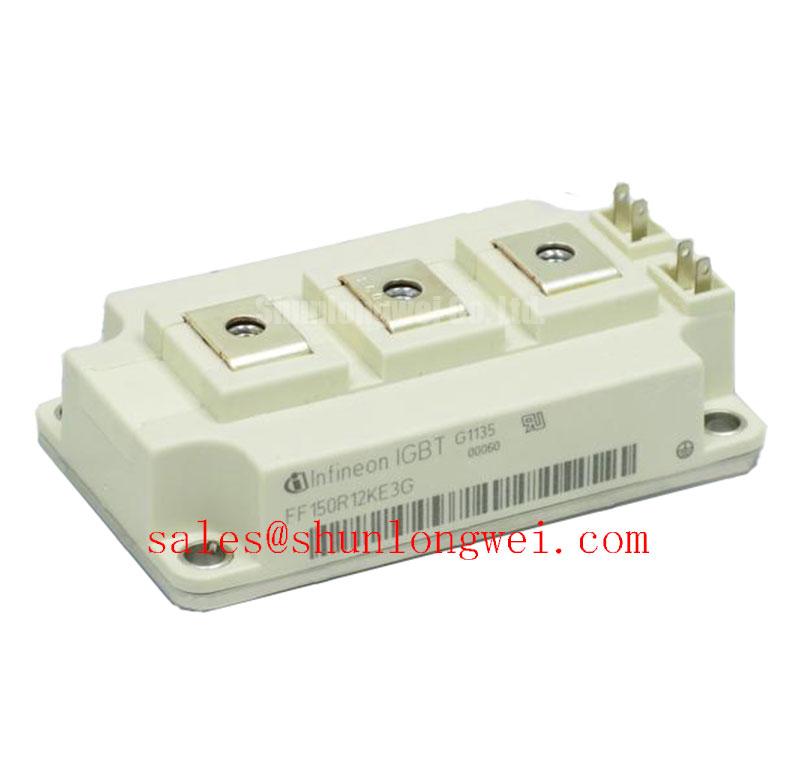
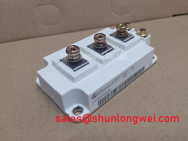
With the DC link isolated and the module discharged, start a thermal investigation by recording the cold mechanical condition, heatsink interface, ambient temperature, and the operating duty that produced the reported fault. The FF150R12KS4 is an Infineon 1200.0 V, 150.0 A EconoDUAL IGBT module; these are official product specifications, not a guaranteed operating point for every inverter topology.
For a heavy-duty variable frequency AC motor drive, switching loss and conduction loss should be treated as separate contributors before they are combined in a thermal model. Conduction loss follows the device voltage drop and current waveform, while switching loss is influenced by bus voltage, load current, gate resistance, commutation path, and switching frequency. The service engineer should capture the actual current and voltage waveforms rather than estimating module stress from the nameplate current alone.
A practical transient thermal model uses a series of resistance-capacitance sections to represent the movement of heat from junction to case and from case into the cooling assembly. Each section represents a time range in which the semiconductor temperature responds differently to a current pulse. For short overloads, the junction temperature can rise faster than the case temperature, so a case measurement taken after the event may understate the peak junction excursion. The model should therefore be correlated with measured case temperature and the real pulse duration.
When a drive trips during acceleration, compare the event record with the current command, PWM state, DC-link condition, and cooling airflow. A single overtemperature indication does not establish the failed mechanism. Uneven thermal compound, a distorted heatsink, inadequate clamping, blocked airflow, or an abnormal commutation loop can produce different electrical symptoms while increasing the same thermal burden.
Layout work should keep the high-current commutation path compact and mechanically stable. The busbar arrangement, return path, and gate wiring need to be considered together because stray inductance can create voltage overshoot during turn-off. The system designer should verify the measured peak voltage against the module voltage boundary during switching tests and then confirm that the thermal model remains valid at the intended overload profile.
Fast semiconductor fuses are normally selected as part of the converter protection system, not as an internal feature of this IGBT module. When a fuse is used, its clearing behavior and I²t coordination should be compared with the converter’s prospective short-circuit energy and the module’s permitted fault response. A fuse that clears too slowly may expose the power stage to destructive energy, while an unsuitable fast fuse can create nuisance interruptions during normal transients.
For phase-controlled rectifier front ends feeding an inverter, the firing angle and conduction interval influence DC-link ripple, input displacement, and harmonic current. The rectifier, DC-link capacitor, braking path, and IGBT bridge should be evaluated as one power system. Passive or active harmonic mitigation may be required by the installation, but the FF150R12KS4 itself should not be described as an EMC or harmonic-compliance solution.
FF150R12KS4 Thermal-Electrical Optimization: Galvanic Gate Drive Isolation, Reinforced Practical Tuning
Verify the gate terminal identity against the original drive drawing before applying any test signal, then trace each gate and emitter connection back to its isolated driver channel. The module’s voltage, current, and EconoDUAL package ratings do not by themselves specify the gate-driver isolation rating, common-mode transient immunity, gate voltage, or recommended gate resistance.
Isolation performance belongs to the complete driver and power assembly. A reinforced isolation barrier, driver CMTI, creepage, clearance, insulation system, and PCB material must be selected and verified for the working voltage, transient environment, pollution level, and enclosure conditions. Do not transfer an isolation value from a different Infineon module or driver board to the FF150R12KS4 without a documented compatibility review.
At the bench, use a suitable isolated measurement arrangement and confirm that the driver output has the expected polarity at the gate-emitter terminals. A floating oscilloscope ground or an incorrectly referenced probe can create a dangerous short path through the power stage. Observe the gate waveform during both turn-on and turn-off, paying attention to unwanted pulses that coincide with collector-emitter voltage transitions.
Spurious triggering can be associated with common-mode displacement, insufficient driver immunity, excessive gate-loop inductance, poor emitter referencing, or coupling from the power bus. The correct response is to compare the suspect channel with a known-good channel under the same switching condition, then inspect the physical gate loop and driver return path. A gate waveform that appears acceptable at low voltage may behave differently at the real DC-link voltage.
Vibration-proof busbar fastening is also an electrical reliability task. Loose joints increase contact resistance and can generate localized heating, while mechanical movement changes parasitic inductance and may disturb gate wiring. Use the original mechanical arrangement where possible, inspect terminal surfaces for contamination or deformation, and apply the equipment manufacturer’s specified fastening method rather than assuming that a generic torque value applies to this package.
Bench Tip: Keep the module protected against ESD, and establish a cold-state reference for diode-mode readings before comparing a suspect unit with another device from the same equipment family.
The broader isolation and power-module context can be reviewed through Infineon’s Infineon HybridPACK™ Drive information, while recognizing that a related product family does not replace the FF150R12KS4 documentation or the drive maker’s isolation requirements.
Benchtop Waveform Tuning: Mitigating Stress via Pollution Degree 3 Creepage Distances on FF150R12KS4
Before waveform tuning, isolate the module from the control electronics and inspect the complete terminal-to-baseplate insulation path for conductive dust, moisture residue, metal particles, and damaged insulating hardware. Pollution Degree 3 is a system installation consideration; it should not be presented as a unique environmental approval of the FF150R12KS4.
An insulation resistance test can help identify a degraded assembly, but the test voltage, duration, connections, and acceptance limit must come from the applicable product documentation and safety procedure. Connect the tester only after all sensitive driver, sensing, and control circuits have been disconnected. Record the temperature and humidity because surface leakage can vary substantially with contamination and moisture.
Do not infer internal substrate integrity from one resistance reading. A stable result should be considered alongside visual inspection, terminal-to-baseplate measurements, phase-to-phase checks where appropriate, and a review of the module’s previous electrical stress. If the reading changes during the test, examine the external insulation path first and then compare the result with an unused or known-good reference under the same test setup.
Creepage and clearance must be evaluated across the complete installation, including busbars, spacers, PCB edges, mounting hardware, cable lugs, and enclosure surfaces. The shortest effective path may occur outside the module body. Dust accumulation can create a conductive film, so enclosure sealing, airflow direction, cleaning intervals, and drain paths belong in the maintenance plan for an industrial drive cabinet.
During switching tests, use a probe arrangement suitable for the voltage environment and keep the measurement loop controlled. A ringing waveform may originate from the commutation layout, probe placement, driver behavior, or load conditions. Change one physical or electrical variable at a time and compare the result with the original trace. This method avoids treating every overshoot as evidence of internal module damage.
For a replacement assessment, the BSM100GAL120DN2 may be reviewed as a separate Infineon module option, but mechanical fit, electrical ratings, terminal arrangement, gate characteristics, thermal interface, and drive settings must be checked independently. A nominally similar voltage class does not establish a drop-in replacement relationship.
FF150R12KS4 Operational Boundaries: Evaluating Multi-Module Parallel Current Sharing Limits
When modules are paralleled, begin by matching the current path rather than assuming that equal nameplate current produces equal dynamic stress. The positive temperature coefficient often associated with IGBT saturation voltage can support steadier static current sharing, but dynamic sharing is strongly affected by gate-loop symmetry, busbar geometry, driver propagation, emitter referencing, and the individual switching characteristics of the devices.
Use physically symmetrical power conductors and gate-drive routes where the converter architecture requires parallel operation. Each branch should experience comparable electrical impedance, thermal conditions, and measurement conditions. The final arrangement should be validated with synchronized current probes and voltage probes during turn-on, turn-off, load transitions, and abnormal operating events.
Static checks can compare the voltage drop and current of each parallel branch at matched temperature and operating conditions. A branch that carries more current may be influenced by busbar resistance, unequal thermal contact, gate timing, sensor placement, or device variation. Treat the measurement as a system observation, then inspect the mechanical and control paths before assigning the condition to one module.
Thermal coupling also affects balance. Modules sharing a heatsink may experience different local airflow or interface pressure, while physically separated modules may see different ambient conditions. The thermal design should use the hottest measured case location and should account for the real duty cycle, including acceleration, regenerative operation, low-speed high-torque operation, and repeated overloads.
In the wider converter topology, a high-current front-end device such as FF300R12KE4_B2 can be evaluated as a separate rectifier or auxiliary-stage component. Its presence does not define the ratings or control requirements of the FF150R12KS4 inverter stage. Engineers should review coordination between rectifier commutation, DC-link ripple, braking energy, and the IGBT switching pattern.
For long-duration qualification, record electrical waveforms, case temperatures, cooling conditions, fault history, and mechanical inspection results as traceable test data. A technology comparison such as The 1200 V CoolSiC™ MOSFET Advantage in Three can provide broader background on alternative switching technologies, but it should not be used to infer the operating limits or lifetime of this Infineon IGBT module.
During field replacement, confirm the original circuit position, terminal orientation, gate-driver compatibility, heatsink contact, and protection coordination before energizing the drive. The FF150R12KS4 provides the defined foundation of a 1200.0 V, 150.0 A EconoDUAL IGBT module; safe operation depends on the verified electrical, thermal, mechanical, and control conditions of the complete variable frequency drive.