


Content last revised on September 10, 2026
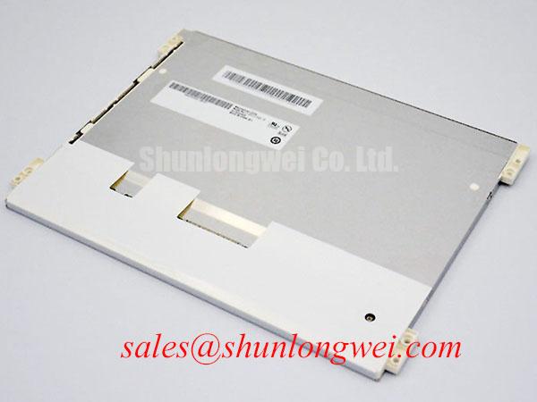
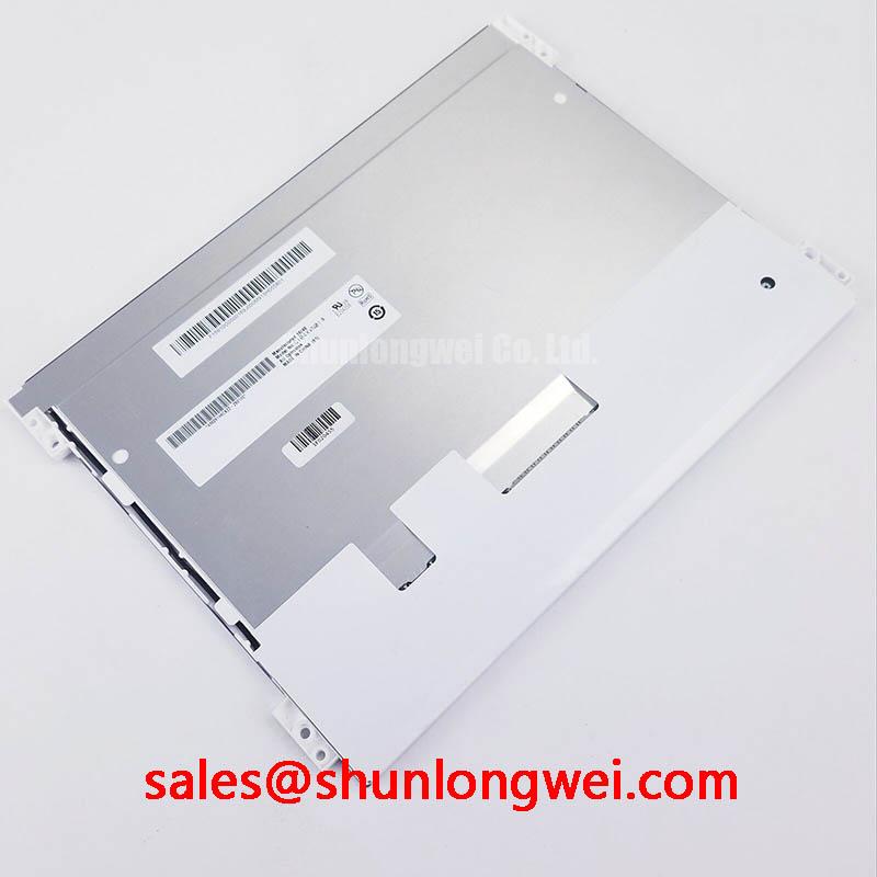
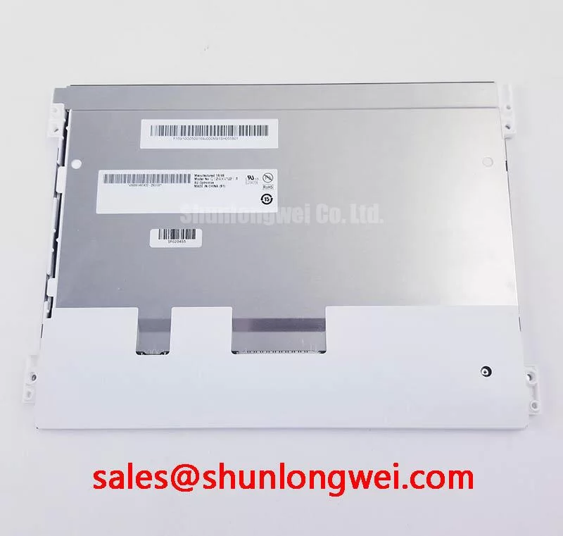
G104XVN01.3 AUO 10.4-Inch Industrial LCD HMI Panel
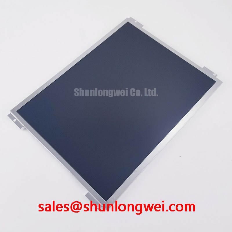
Begin a replacement inspection by confirming the panel nameplate, checking the connector and bezel for mechanical damage, and comparing the cold resistance readings of the unpowered display assembly with a known-good unit. The G104XVN01.3 is an AUO TFT-LCD display module classified for industrial LCD and HMI panel use. System engineers should confirm the complete electrical and mechanical interface from the original panel documentation before installation.
| Model | G104XVN01.3 |
| Manufacturer | AUO |
| Product category | Industrial Grade LCD/HMI Panel |
| Package or enclosure | TFT-LCD Display Module |
This product page is intended for engineers assessing a display replacement in an industrial automation CNC operator panel or robot teach pendant. The listed product information confirms the product category and module construction, but it does not by itself establish connector pinout, logic supply, resolution, viewing angle, backlight architecture, touch function, or mounting dimensions. Those values must be matched against the equipment service file, the original panel label, and the applicable AUO documentation.
Single Vertical Hairline Defect and Sub-Pixel Column Driver Open-Circuit Localization
A single persistent vertical line should be examined before the panel is removed from its enclosure. First, display solid red, green, blue, white, black, and mid-gray test fields through the original controller. Record whether the line remains at the same coordinate and whether its visibility changes with image content. Second, inspect the surface and frame under controlled illumination. A 45-degree flashlight inspection with the display showing a dark field can help distinguish a surface mark, optical nonuniformity, or backlight-related shadow from a line generated by the pixel addressing path. Third, compare the suspected area with the same image output on a known-good display or with the controller’s test pattern.
This three-stage check is an engineering diagnostic method, not a factory failure threshold for the G104XVN01.3. A line that remains sharply aligned through primary-color patterns may justify closer examination of the column addressing path, flexible interconnect, or bonded driver region. A soft vertical variation that changes with viewing angle or ambient light may require optical and mechanical inspection instead. Do not press the active area or bonded edge while powered, because pressure can alter the symptom and make the result difficult to reproduce.
For equipment exposed to servo drives, switching power supplies, and motor cabling, the signal path should be reviewed at the same time. Differential routing should preserve a controlled return path and minimize avoidable discontinuities at the panel connector. A 100-ohm differential characteristic impedance with a 10 percent tolerance is a common engineering target for LVDS links, but it is a Design Consideration, not a confirmed internal specification of this exact module. Pair skew should also be controlled according to the transmitter, receiver, cable, and timing budget. If a 50 picosecond limit is required by the selected interface, it must be treated as a system-level verification value rather than an AUO factory claim for this product.
Use an oscilloscope at the controller and panel ends when the defect appears intermittently. Compare common-mode behavior, edge shape, ringing, and the differential eye against the known-good signal path. A damaged cable, connector contact variation, grounding problem, or electromagnetic coupling can produce symptoms resembling a display driver fault. The panel should only be condemned after the supply, cable, controller output, and mechanical seating have been checked under the same operating condition.
20-Pin or 30-Pin Differential LVDS Timing, Pixel Clock, and Skew Compensation
Do not select a replacement cable by appearance alone. The G104XVN01.3 product designation identifies the display module, but the available factory data supplied for this page does not confirm whether the installed assembly uses a 20-pin or 30-pin connector, a particular LVDS mapping, a TTL interface, or a specific backlight input. The system integrator should verify the required supply voltage from the original panel documentation and confirm connector keying, pin numbering, enable signals, backlight control, and return paths before applying power.
Power sequencing should be observed with the panel disconnected from the controller during the first electrical check. Confirm that the logic rail rises cleanly, remains within the original equipment limits, and does not show excessive overshoot or repeated restart behavior. A rise-time window such as 0.5 milliseconds to 10 milliseconds may be specified by a particular controller or panel family, but it is not an official G104XVN01.3 value in the supplied parameter set. Designers should therefore verify the actual timing requirement from the applicable panel documentation rather than transfer a value from a similar AUO model.
When the interface is LVDS, the receiver must see the expected data mapping and clock relationship. JEIDA and VESA mappings are not interchangeable assumptions; an incorrect selection can create swapped color levels, abnormal grayscale, split-screen images, or unstable synchronization. Confirm the bit allocation, channel order, pixel depth, and clock polarity from the original configuration. If the existing control board offers a mapping selector, document its position before replacement and verify the result with a full-color test image.
Clock jitter and data hold behavior should be evaluated across the equipment’s real temperature range. This is an Engineering Recommendation based on interface integrity principles, not a claimed AUO timing guarantee. Use the controller datasheet and panel timing documentation to establish the allowable margin, then observe the differential clock and data at the receiving connector. When the symptom changes after the cabinet door is closed, the investigation should include cable routing, shield termination, chassis bonding, and proximity to high-frequency servo conductors.
The G104VN01 V1 can be reviewed as a same-size or same-resolution reference during compatibility analysis, but a reference model is not an automatic substitute. Connector assignment, optical stack, timing, mounting envelope, and backlight control must be compared item by item. A controller that works with one AUO display may still require configuration changes for another display family.
Industrial Bezel Mechanical Envelope Tolerances and Mounting Screw Torque Optimization
Before fitting the module into a CNC operator panel or robot teach pendant, measure the opening, support ledges, connector clearance, cable bend path, and rear-cover interference using the original assembly as the reference. The supplied product information confirms a TFT-LCD display module but does not provide the panel outline, active-area dimensions, mounting-hole pattern, or bezel tolerance. Those dimensions must be taken from the relevant mechanical drawing or checked against the removed unit.
Mechanical loading should be distributed across the bezel rather than concentrated at one corner. A cross-pattern tightening sequence is a useful Design Consideration for reducing uneven frame stress, but the correct fastener size and torque remain dependent on the chassis, insert, washer, gasket, and mounting bracket. A specific torque range must not be presented as an official G104XVN01.3 mounting limit without supporting documentation. Engineers should use the equipment manufacturer’s assembly specification and validate the result on the complete enclosure.
Uneven compression can produce localized optical nonuniformity, edge brightening, dark-field patches, or temporary changes in the visible image. These observations should be checked with the panel both installed and released from the frame, while avoiding direct pressure on the active area. If the defect changes when a screw is loosened, that is evidence for a mechanical interaction requiring further inspection; it is not proof of a particular internal optical construction.
The sealing interface also deserves attention in dusty factory environments. Check that the bezel gasket lies flat, has no cuts, and is not folded across a connector or ventilation path. The surrounding metalwork should not obstruct the display’s rear clearance or force the module against a cable. When the display is installed behind a protective window, verify that the window, gasket, and panel remain aligned through the expected thermal movement of the enclosure.
For a broader explanation of external interfaces, display timing, and selection issues, engineers can consult The Ultimate Guide to Industrial TFT LCD Technology. This reference can support system-level review, while the exact G104XVN01.3 installation remains governed by its applicable documentation and the host equipment drawings.
⚠️ Maintenance Note: Inspect the bezel gasket and cabinet airflow path during scheduled service, and disconnect power before removing the display cable or opening the panel enclosure.
Dynamic Contrast Stabilization and Liquid Crystal Birefringence Temperature Tracking
Image evaluation should be performed after the display has reached a stable operating condition in the actual enclosure. Record black, white, and mid-gray fields at the normal operator position, then repeat the check from several practical viewing directions. A contrast change that varies with temperature, viewing angle, or ambient illumination should be separated from a controller gamma problem, backlight uniformity issue, window reflection, or mechanical pressure effect.
The supplied factory information does not confirm whether the G104XVN01.3 uses TN, IPS, or MVA technology, nor does it specify a viewing cone such as 85 degrees in four directions. Those characteristics must not be assigned to this model without the applicable AUO datasheet. In a system using a TN panel, grayscale inversion and color shift can require viewing-angle and gamma verification. IPS or MVA references may be relevant during a neutral optical comparison, but they do not establish the construction of this product.
Temperature tracking is particularly important when a display is mounted near cabinet power components or enclosed behind a protective window. Check for condensation risk during cold start, rapid ambient changes, and shutdown. The enclosure design should provide a controlled thermal path without directing concentrated hot air onto one region of the display. Backlight uniformity should be assessed using white and gray fields after the panel has stabilized, looking for gradual brightness drift as well as localized bright or dark areas.
High ambient light can make a normal black level appear raised. Surface treatment, protective glass, viewing angle, and reflections from the operator panel all influence perceived contrast. Anti-glare performance should therefore be assessed with the same lighting, window, and cleaning condition used in service. Do not describe a display as having a particular AG etching process unless that construction is confirmed by the manufacturer’s documentation.
Touch functionality must also be verified independently. The available product data identifies the item as a TFT-LCD display module and does not confirm an integrated resistive or capacitive touch layer. If the CNC panel or teach pendant requires gloved operation, wet-touch response, or a separate touch controller, the system integrator should verify those functions from the original assembly documentation and test them with the intended gloves, cleaning method, protective window, and interface electronics. The TCG121WXLPAPNN-AN20-S may be reviewed as a related display solution within a broader system topology, but interface and optical compatibility still require direct engineering verification.
During final commissioning, compare the replacement against the original image settings, gamma behavior, backlight level, and controller timing. Record the tested cable configuration and enclosure condition so that later maintenance staff can distinguish a panel issue from a change in the host control system. This approach supports practical evaluation of the G104XVN01.3 AUO TFT-LCD display module without assigning unverified electrical, optical, or mechanical values to the product.