Content last revised on September 10, 2026
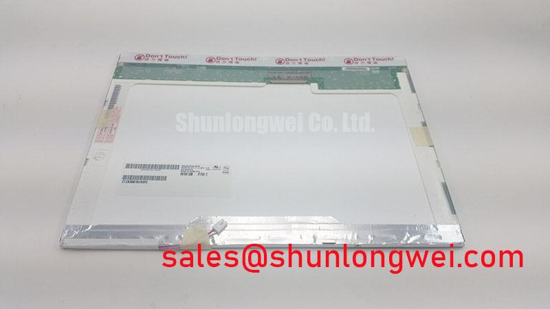
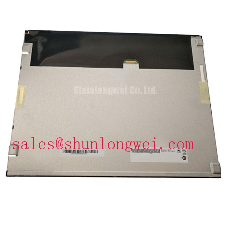
AUO G141I1-L01 Industrial TFT LCD Display Module
Before installing the replacement, isolate the equipment, inspect the display connector and bezel, and compare the panel label with the required G141I1-L01 part number. The available factory information identifies this product as an AUO industrial-grade LCD/HMI panel supplied as a TFT-LCD display module. Its official factory specification status should be confirmed against the original equipment documentation before electrical commissioning.
For maintenance engineers, the main task is interface and mechanical compatibility. The display module should be checked against the existing controller, cable arrangement, mounting aperture, bezel clearance, backlight control method, and enclosure conditions. The supplied product data does not confirm resolution, active-area dimensions, logic voltage, connector pinout, viewing-angle rating, luminance, or operating-temperature limits. Those values should not be assumed from the model number alone.
| Parameter | Available specification | Integration status |
|---|---|---|
| Model | G141I1-L01 | Official product identification |
| Manufacturer | AUO | Official manufacturer identification |
| Product category | Industrial Grade LCD/HMI Panel | Official category description |
| Construction | TFT-LCD Display Module | Official module classification |
| Specification status | Factory identification available; full specifications require verification | Verify revision-specific data before installation |
When the original panel documentation is unavailable, the system integrator should record the installed unit’s cable orientation, connector keying, display timing, supply requirements, backlight wiring, and mechanical reference points before removal. This creates a practical comparison record without treating unconfirmed values as manufacturer specifications.
High-Humidity Storage Margins and Delamination Prevention Protocols
For a panel removed from service or held as a maintenance spare, storage inspection should begin with the packaging condition, surface cleanliness, connector protection, and perimeter sealing area. Moisture exposure can affect optical appearance, connector contacts, adhesive interfaces, and the enclosure around the display. The official information supplied for G141I1-L01 does not establish a humidity rating, storage limit, thermal-cycle rating, epoxy construction, or delamination-life figure. These conditions must therefore be taken from the applicable AUO documentation or the original equipment specification.
A high-humidity storage review should look for visible haze, edge lifting, contamination beneath the front surface, uneven optical regions, corrosion near the connector, and evidence that the panel has been compressed against a damp packing material. These observations are screening actions rather than proof of a single failure mechanism. If an optical defect is found, compare the module with a known-good display under the same image pattern and illumination, then document whether the appearance changes with temperature or viewing angle.
Sub-zero operation requires particular care because liquid-crystal response can become slower as temperature falls. The supplied product data does not confirm an operating range such as −30°C to +85°C, a gray-to-gray response specification, or a heater requirement for this model. Engineers evaluating the panel in outdoor or semi-enclosed equipment should verify the specified cold-start behavior, warm-up requirements, display timing, and condensation controls from the correct revision of the panel documentation.
Direct sunlight also requires measured validation rather than assumption. An integrator should evaluate image readability, contrast, reflections, and surface glare at the actual installation angle and ambient light level. No official contrast-ratio or anti-glare performance value is included in the supplied factory data, so a value such as 500:1 under a defined lux level must not be assigned to this model without a supporting source.
Mechanical sealing is equally important. The bezel gasket should contact the enclosure evenly, with no folds, gaps, contamination, or local compression points. Fasteners should be tightened progressively in a cross-pattern when the equipment design allows it, while the final torque remains governed by the enclosure manufacturer’s service documentation. Uneven pressure can distort the display stack or create visible non-uniformity, but the exact optical effect depends on the mechanical construction and mounting geometry.
⚠️ Maintenance Note: Inspect the display gasket and cabinet airflow path during scheduled service so dust, moisture, and trapped heat do not accumulate around the module.
Viewing-Cone Evaluation for Multi-Angle Operator Consoles
Multi-angle operator consoles should be assessed from the actual viewing positions used by the driver, service technician, or control-room operator. The supplied specification classifies G141I1-L01 as an industrial TFT-LCD display module, but it does not confirm Super-IPS, MVA, TN, or any other panel technology. It also does not confirm a symmetric viewing angle such as 85° in four directions. These characteristics must be verified from the original AUO data sheet or measured on the exact panel revision.
A practical evaluation uses the same test images at normal brightness and at the expected cabin illumination. Check grayscale steps, dark detail, color shift, reflected glare, and readability from above, below, and both sides. A change in contrast or color at an oblique angle may reflect the panel technology, optical stack, viewing direction, or installation environment. It should not be treated as evidence of a particular internal construction without documentation.
For a telematics display in heavy earthmoving equipment, vibration and bezel loading should be assessed together with viewing performance. The mounting frame should support the display without forcing the glass or applying point pressure near the corners. Cable routing should leave sufficient movement allowance for the equipment’s service procedure while preventing the harness from pressing against the panel edge or connector.
If the host system uses a digital video interface, the system designer should verify the actual signaling standard, data mapping, cable length, grounding arrangement, and controller timing. Differential routing guidance may apply to the host electronics, but the supplied product information does not confirm a differential input or a specified characteristic impedance for this module. A nominal 100 ohm routing target should not be presented as a G141I1-L01 factory requirement unless the interface documentation explicitly states it.
At the bench, compare the suspected panel with the original controller and a known-good display. Check whether the image fault follows the panel, the cable, the controller output, or the power and backlight path. An intermittent image, color imbalance, or split-screen appearance may involve several parts of the signal chain, so oscilloscope measurements and cable substitution should be used before assigning a cause.
For broader enclosure, vibration, sealing, and industrial HMI evaluation practices, maintenance teams can consult Industrial Display & HMI Solutions as a separate engineering reference. That resource should support system assessment and does not replace the model-specific AUO documentation.
Backlight and Dimming Verification for Industrial HMI Service
Backlight compatibility is a critical replacement check because a display module and its host controller must operate as one electrical assembly. The supplied factory information identifies the unit as a TFT-LCD display module but does not confirm whether the installed version uses a WLED assembly, CCFL technology, an integrated driver, an external inverter, a constant-current input, or a defined PWM control range. The system integrator should verify the required backlight supply and control method from the original panel documentation.
Do not infer a 1000:1 PWM dimming ratio, a specified PWM frequency, a half-life rating, or an MTBF figure from the product category. Those are model-specific or system-specific claims that require an authoritative source. A maintenance engineer can still perform a useful functional check by observing startup brightness, uniformity, dimming response, connector temperature, audible noise, and any visible flicker at the host system’s normal settings.
If the replacement is being considered for an operator display in a heavy mining shovel or earthmoving equipment telematics cabin, measure the real cabinet supply during startup and during changes in machine operating state. Confirm that the backlight enable signal reaches the expected state only after the host controller has completed its own initialization. A dark screen may arise from the panel, the backlight driver, the enable line, the supply path, or the controller’s sequencing logic; the repair record should distinguish these test points.
Cold environments can increase display response time and can also affect the behavior of the external backlight driver. The supplied product data does not confirm a cold operating limit, gray-to-gray response curve, heater-strip interface, or condensation-control circuit. If the equipment is exposed to rapid temperature changes, the enclosure design should manage moisture and allow the panel to reach a stable operating condition before demanding full display performance.
Where the existing system includes a separate inverter or LED driver, verify connector polarity, enable logic, current regulation, fault reporting, and physical clearance. Substituting a driver solely because the connector appears similar can produce an electrically incompatible assembly. The correct decision should be based on the original wiring diagram, measured signals, and the revision-specific panel interface data.
For a neutral comparison during maintenance planning, engineers may review the same-size or same-resolution compatibility candidate TCG121WXLPAPNN-AN20-S. This link is provided for comparative evaluation only; the system designer must verify dimensions, timing, connector details, and electrical compatibility before considering any alternative.
TTL RGB Bus and Logic Power Rail Verification
Before connecting G141I1-L01 to a replacement controller, identify the host interface from the original wiring documentation and confirm every signal by pin number and connector orientation. The available official product data does not provide a TTL RGB pinout, logic supply voltage, power-on timing, JEIDA or VESA mapping, differential interface specification, or backlight control definition. The system integrator should verify these details from the original AUO panel documentation rather than selecting between possible voltage or bus arrangements by assumption.
A correct startup check should monitor the panel supply, ground reference, display-enable signal, backlight-enable signal, and video activity with the panel disconnected first where the equipment service procedure permits. The rise-time window, reset behavior, and enable order must come from the applicable interface specification. Values such as a 3.3 V or 5.0 V logic rail and a defined millisecond power-on interval should not be assigned to this model without documented confirmation.
Image mapping requires the same discipline. If the host uses parallel RGB data, verify color-bit order, pixel clock polarity, line timing, frame timing, and the relationship between display enable and active video. Incorrect mapping can appear as color inversion, misplaced image data, unstable synchronization, or a divided image. Such symptoms may indicate a timing or wiring mismatch, but they should be checked against a known-good signal path rather than attributed to the panel alone.
Grounding and cable routing should be reviewed when the module is installed near variable-speed drives, contactors, high-current conductors, or radio equipment. Keep the video harness separated from noisy power wiring where the cabinet layout allows, provide a controlled return path, and verify shield termination according to the host equipment design. EMC performance belongs to the complete assembly and installation; the LCD module itself should not be represented as independently certified for a machine-level EMC standard.
After installation, run a controlled image test while monitoring supply stability and connector retention. Confirm that the bezel does not load the glass, that the cable is not sharply folded at the connector, and that the image remains stable during normal cabinet vibration. Record the panel revision, controller revision, cable identification, and measured interface conditions in the maintenance log so future replacement work can be performed against verified installation data.