

Content last revised on September 10, 2026
Backlight Driving, PWM Dimming and Flicker Evaluation
The supplied factory data for the G170EG01 V1 does not confirm a WLED backlight, a constant-current input, a 1000:1 PWM dimming ratio, a PWM frequency range, or a specific half-life value. Those features must not be assigned to this model without the applicable AUO datasheet or original equipment service record. In a repair cabinet, the first practical task is to identify how the removed panel was powered. Trace the backlight cable to the host board and determine whether the board contains a dedicated LED driver, a lamp inverter, or a separate display power stage. The connector style alone is not sufficient evidence.
When the original system uses a constant-current backlight driver, the driver should be evaluated as part of the complete display assembly. Its output compliance, current regulation, enable signal, dimming method, start-up sequence, and fault response should match the panel documentation. Applying an assumed LED current to an unverified panel can create excessive optical stress or prevent the backlight from starting. The system integrator should verify the required supply voltage from the original panel documentation rather than selecting between commonly used voltage options by assumption.
PWM dimming is also a system-level matter. If the host controller provides PWM, engineers should confirm the accepted logic level, frequency window, duty-cycle behaviour, and enable timing from the panel and driver documentation. A practical bench check uses a known-good controller and an oscilloscope to compare the dimming waveform, backlight current, and visible brightness response. Audible noise, unstable brightness, or intermittent start-up may involve the driver, wiring, grounding, or control timing; the symptom should be compared with the known-good signal path rather than assigned to the LCD panel alone.
For railway passenger information displays or cab signalling screens, flicker evaluation should be performed at the installed viewing distance and at the intended brightness range. Camera-based inspection can reveal modulation that is not obvious to the eye, but the result depends on camera exposure and frame rate. This is a Design Consideration for the complete display system and is not an AUO factory performance claim for the G170EG01 V1.
Thermal Cycling, Polarizer Adhesives and Sealant Gasket Integrity
No operating temperature range, storage temperature range, polarizer adhesive specification, perimeter sealant construction, LED half-life, or MTBF figure is included in the confirmed product data supplied for this page. A maintenance engineer should therefore treat thermal capability as a documentation and qualification item, not as an assumed attribute of the model. The original equipment manual, panel datasheet, and system environmental specification should be checked together because the enclosure temperature can differ substantially from the surrounding cabinet temperature.
During a cold start, allow the display assembly to reach a stable, dry condition before applying power if condensation is possible. Moisture can form when a cold panel is moved into a warm, humid service area or when a sealed cabinet undergoes rapid temperature change. Inspect the perimeter gasket for compression set, gaps, tears, contamination, and loss of adhesion. The gasket should contact the intended chassis surface continuously without being folded into the optical opening. Any replacement seal should be selected for compatibility with the enclosure design and service environment; the supplied data does not identify a specific gasket material or thickness.
Liquid crystal response at low temperature can change because viscosity and switching behaviour are temperature dependent. If characters appear slow, smeared, or uneven during cold operation, record the panel temperature and compare the result with the original unit or approved environmental limits. This observation may involve the panel, timing controller, supply stability, or image content. A controlled temperature test with a fixed test pattern is more useful than judging motion response from a changing operator interface.
Thermal cycling should include visual inspection after each defined test stage. Check for new edge light leakage, local brightness variation, bubbles, delamination, connector movement, and changes in the gasket contact line. Claims such as a 50,000-hour backlight half-life or a guaranteed MTBF require an identifiable manufacturer specification or qualification report. They should not be inferred from the product category or from general LED industry expectations.
Maintenance Note: Inspect cabinet airflow paths and the display gasket during scheduled service, especially after repeated cold starts or enclosure work.
The Industrial Display and HMI Solutions resource can be used as broader integration context, while model-specific environmental limits should remain controlled by the AUO documentation for the G170EG01 V1.
Flush-Mount Open-Frame Bezel Integration and Perimeter Gasket Shock Isolation
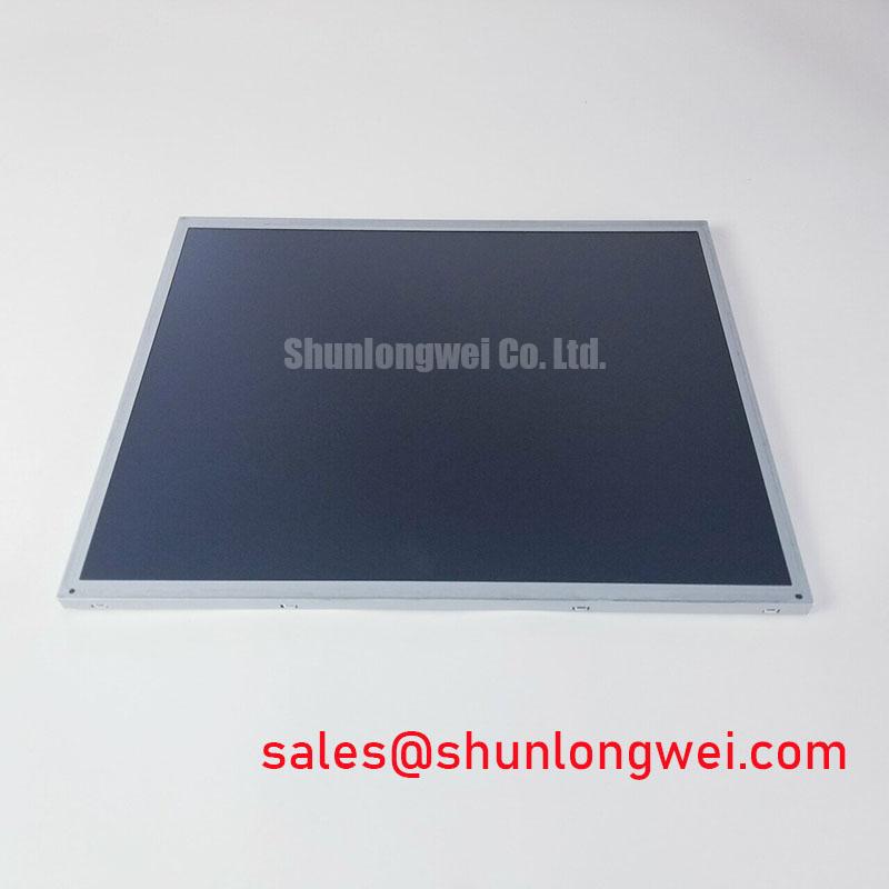
The confirmed information identifies the G170EG01 V1 as a TFT LCD Display Module but does not specify its outer bezel dimensions, active-area dimensions, mounting-hole pattern, fastener size, allowable chassis tolerance, connector location, or approved mounting torque. These values must be measured from the original assembly or obtained from the model-specific mechanical drawing. A panel should not be forced into a cut-out because a small mismatch can transfer stress into the glass, bezel, connector, or optical stack.
For flush mounting, first confirm the chassis opening against the panel’s approved envelope. The display should be supported by the designated mounting surfaces, with the gasket seated evenly around the perimeter. Mechanical loads should be distributed across the frame rather than concentrated near a corner or beside the connector. If fasteners are used, apply the manufacturer’s specified torque and tightening sequence. A cross-pattern sequence may be a useful Design Consideration for distributing load, but the value itself must come from the panel or equipment service specification. The previously suggested generic M3 torque range is not an official G170EG01 V1 parameter and should not be treated as a universal limit.
After installation, inspect the screen with a uniform grey and white test pattern at several brightness settings. Localised dark areas, edge brightness changes, or pressure marks may be associated with uneven mounting stress, chassis distortion, gasket displacement, or panel damage. The inspection should be repeated after the equipment has reached its normal operating temperature. Do not attempt to correct optical non-uniformity by tightening fasteners beyond the documented mechanical limit.
The display signal path also requires verification. The supplied product information does not confirm LVDS, TTL, eDP, connector pinout, differential impedance, skew allowance, clock timing, or hold-time specifications. If the original system uses a differential interface, preserve the existing controlled routing and cable orientation during service. Minimise unnecessary cable length and avoid routing the display cable alongside high-current switching conductors where the cabinet layout permits. These are Design Considerations for reducing signal disturbance, not confirmed electrical ratings for this model.
Before final closure, check that the connector is fully seated, the cable bend radius is respected according to the cable supplier’s requirements, and the metalwork does not press against the cable or panel edge. The display should be operated through power cycling, full-screen colour patterns, text rendering, and the actual equipment interface before the bezel is permanently sealed.
EMI Evaluation, Chassis Shielding Continuity and Common-Mode Ferrite Chokes
The G170EG01 V1 factory information supplied here does not include an EMC immunity rating, shield termination specification, LVDS clock jitter limit, TTL timing table, common-mode choke requirement, or certification statement. A TFT LCD display module should therefore be evaluated within the complete host equipment. The panel itself cannot be represented as independently passing a system-level CISPR, EN 55011, railway, or other EMC approval.
When a display is installed near variable-frequency motor drives or other high-current switching equipment, begin diagnosis by separating image data, backlight power, and cabinet protective-earth paths in the wiring review. Inspect the cable shield termination at both ends and confirm that the chassis bonding method follows the equipment design. A shield that is connected through a long improvised pigtail, a painted mounting surface, or a loose fastener may behave differently from the intended enclosure bond. The correct termination method remains system dependent and should be validated during the equipment’s EMC test.
Common-mode ferrite components can be considered when measured interference is coupled onto the display cable, but they should not be added blindly. The engineer should compare the signal waveform before and after the component, check for unwanted edge slowing, and confirm that the added part does not disturb the interface’s required timing or amplitude. Pixel jitter, horizontal bands, or intermittent image loss may also originate from the host transmitter, power rail noise, connector contact, grounding, or software timing. Use an oscilloscope and a known-good signal path to distinguish these possibilities.
For a railway passenger information system or cab signalling display, the replacement assessment should include the host controller, cable assembly, backlight driver, enclosure, and power sequencing. Confirm that the panel wakes correctly after cold start, recovers after a communication interruption, and remains stable during the equipment’s normal switching events. If the original documentation does not identify the interface or timing requirements, obtain those details before connecting the G170EG01 V1 to a live controller.
Procurement records should retain the exact model designation, revision suffix, mechanical drawing, electrical interface record, and inspection results for the replacement evaluation. This documentation supports future maintenance decisions without assuming that a visually similar LCD panel has the same electrical or mechanical characteristics.