

Content last revised on October 4, 2026
Product Identification and Replacement Checks
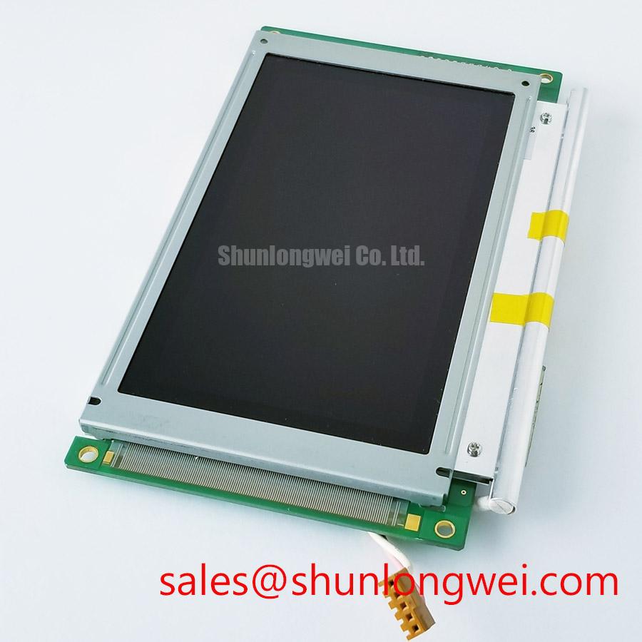
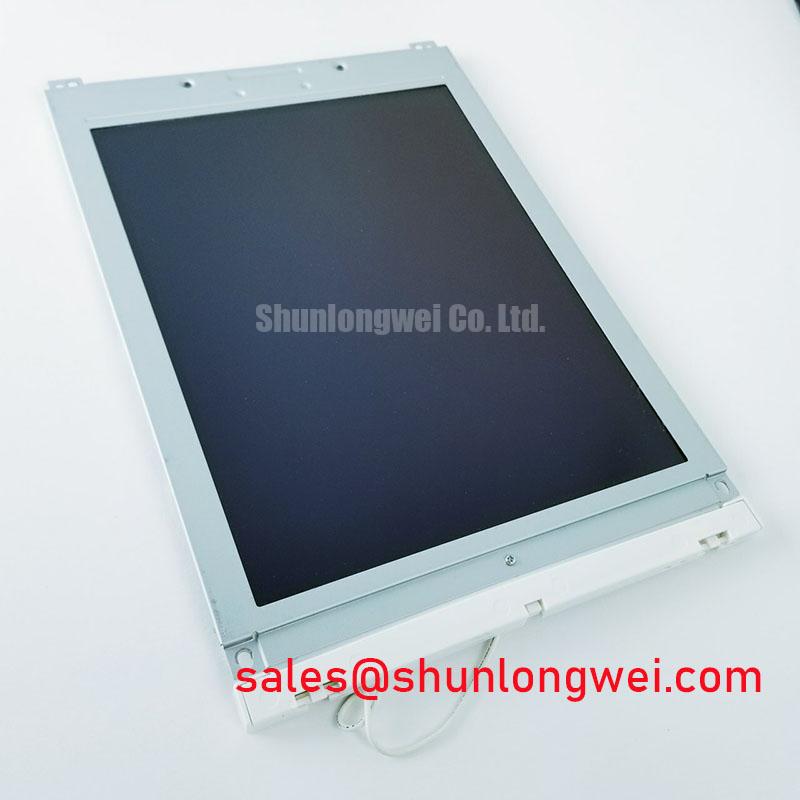
Inspect the bezel and connector of the removed display before evaluating DMF-50260NFU-FW-23 as a replacement. Record the label, connector orientation, mounting points and visible image fault while the original installation is still documented. The supplied product identification lists this Kyocera / OPTREX unit as an industrial LCD/HMI panel in a TFT-LCD display module form. It does not establish the connector pinout, electrical ratings, optical performance or internal construction needed to approve an installation.
Single Vertical Hairline Defect and Column-Fault Localization
Begin with a controlled image test rather than treating a thin vertical line as proof that the panel itself has failed. Display full-screen red, green and blue fields, then compare the line’s position, color and continuity across each field. A line that remains fixed at the same column deserves a different investigation from a defect that moves with the video content. Photograph each field under consistent exposure so that the receiving engineer can distinguish a persistent panel-area feature from a rendering or capture artifact.
Next, check whether the mark is visible with the image source disconnected or with the backlight off, where the host design permits those tests. Under controlled lighting, a flashlight held obliquely to the screen can help reveal whether image information is present in an apparently dark region. That observation can separate a possible illumination problem from a video-path problem, but it cannot identify a specific failed internal bond or driver. A suspected column-driver fault should be assessed against the original panel documentation and a known-good signal path before the display is condemned.
For a repair assessment, trace the fault outward as well as inward. Reseat an accessible connector only after the equipment has been made safe, inspect the cable for mechanical damage, and compare the host’s test pattern with the panel image. If the fault changes when the source or cable changes, the evidence points away from an exclusively panel-local defect. If it stays fixed, record that result without assigning an unverified internal failure mechanism to this model.
Bright ambient light can make a faint line easier to notice while making dark-field defects harder to judge. Test readability in the intended enclosure and lighting conditions, including reflected light from the cover window. No contrast ratio at a specified sunlight level or anti-glare treatment is established by the supplied product data, so neither should be entered as a DMF-50260NFU-FW-23 acceptance criterion without the original optical specification.
Chassis Fasteners, Bezel Clearance and Optical Mura
Before tightening a replacement display into an HMI chassis, compare its outer envelope with the removed unit and the equipment drawing. Check the bezel opening, connector exit, cable bend space, bracket contact areas and whether a cover window presses on the active display region. Matching the visible screen area alone does not establish mechanical interchangeability. The mounting geometry and permitted clearances must be verified against the original panel and enclosure documentation.
Uneven pressure can produce localized brightness or color variation known as mura. If a dark-field pattern changes after the chassis is assembled, loosen the accessible restraints in accordance with the equipment service procedure and repeat the observation. A change associated with assembly pressure is useful diagnostic evidence; it does not, by itself, identify the affected internal layer. Inspect for debris, distorted brackets and contact between the bezel and surrounding structure before changing any mounting method.
💡 Pro Tip: Do not apply an assumed M3 torque to DMF-50260NFU-FW-23; confirm the fastener size and tightening limit from the panel and chassis drawings first.
A cross-pattern tightening sequence can be considered when the approved mounting arrangement uses multiple fasteners, because it helps the technician observe whether clamping changes the image. The actual torque and any gasket compression limit remain system-determined. For an equipment evaluation, such as a heavy mining shovel telematics display, the enclosure’s retention and vibration requirements also need review; the application example does not establish that this panel has a particular vibration rating.
Brightness decline during service should be evaluated through repeatable measurements, not an assumed backlight lifetime. Record the image pattern, brightness setting, supply conditions and panel temperature at each comparison. The supplied identification does not specify a backlight type, drive method or lifetime curve. Broader display-aging concepts and test terminology are discussed in The Ultimate Guide to Industrial TFT LCD Technology; model-specific service limits still require the original documentation.
Viewing Direction, Grayscale and Video-Interface Alignment
Mounting a panel in the correct orientation matters when an operator views it from above, below or off to one side. Place a grayscale ramp on the screen and inspect it from the positions permitted by the equipment layout. Look for tones that become difficult to distinguish, apparent inversion or a change in color with viewing angle. These are observations to compare with the original unit, not evidence that DMF-50260NFU-FW-23 uses a particular liquid-crystal mode. Its normally white behavior, viewing cone and surface treatment are not confirmed by the supplied specifications.
If grayscale appears wrong even when viewed straight on, investigate the video path before attributing the result to the LCD. Compare the host configuration and original panel documentation for timing, color-bit mapping and any stated data format. JEIDA and VESA mapping describe distinct ways a compatible LVDS system can assign color bits; selecting the wrong mapping can alter displayed tones. Neither an LVDS interface nor a JEIDA or VESA mapping is verified for this model, so the system integrator must confirm the actual interface and pinout before connecting a controller.
The same boundary applies to transmission-line design. If the documented interface is differential, route and terminate its pairs according to that interface specification, then check signal integrity and timing at the installed connector. Control pair-to-pair skew where it affects clock and data alignment, particularly when a cable passes near switching equipment. A particular differential impedance or skew allowance cannot be assigned to this module without its electrical specification and the host timing budget. If the documented interface is not differential, an LVDS routing rule is not an appropriate substitute for its requirements.
A display controller’s timing and grayscale settings can also influence the observed image. Compare the host configuration with the original panel requirements for pixel timing, power sequencing and any specified gamma or grayscale setup. Do not adjust controller values to conceal a mechanical or cabling fault before recording the original state. The system integrator should verify the required supply voltage from the original panel documentation; the supplied product identification provides no voltage value to use as a commissioning setting.
If the finished HMI includes touch input, assess that assembly separately. A glove-use or wet-surface test concerns the installed touch sensor, controller, cover window and software settings. No capacitive or resistive touch layer is identified in the supplied specifications for DMF-50260NFU-FW-23. Likewise, apparent image disturbance near servo equipment calls for checks of cable routing, grounding and the host signal path rather than an unsupported EMC claim for the LCD module.
Edge Temperature, Illumination Checks and Service Integration
After the display is installed, examine the illuminated image for edge-localized bright or dark areas and compare it with the pre-installation record. If a change appears only after the enclosure reaches operating temperature, measure accessible temperatures and inspect whether brackets, seals or nearby heat sources have altered the panel’s operating conditions. Keep those observations tied to the complete assembly: the supplied data does not confirm a high-nits rating, an edge-lit LED arrangement, a PMMA light guide or a material-specific temperature limit for this module.
Where the equipment drawing provides for a heat spreader or thermal rail, verify its contact surfaces and clearance against that drawing rather than adding pressure to the display bezel. Any change intended to reduce an edge hot spot should be checked for its effect on image uniformity and connector clearance. Thermal design remains a system-level decision, subject to the panel’s documented limits and measurements in the operating enclosure.
If illumination varies with a brightness command, record the command level, visible response and relevant host measurements before adjusting the driver. The original panel documentation must establish whether a separate backlight supply or control input exists and what it requires. A lifetime designation such as L70/B50 is not a verified rating for DMF-50260NFU-FW-23; it should not be used to predict replacement intervals without a model-specific source and defined test conditions.
Complete the integration check with the screen fitted as it will be used: verify that the connector remains fully engaged, the cable does not bear on the chassis edge, the full image remains visible through the aperture, and the startup and shutdown sequence follows the documented panel requirements. Compare the final grayscale and primary-color patterns with the bench record. That comparison gives the repair team an actionable account of what changed during assembly without turning an unverified interface, optical figure or service-life estimate into a product specification.