

Content last revised on September 10, 2026
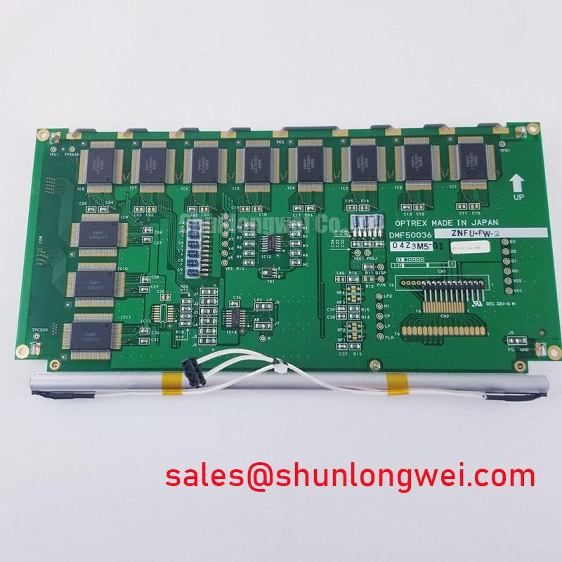
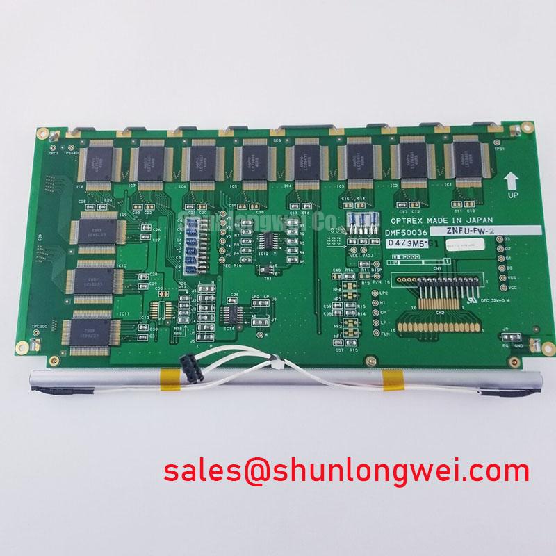
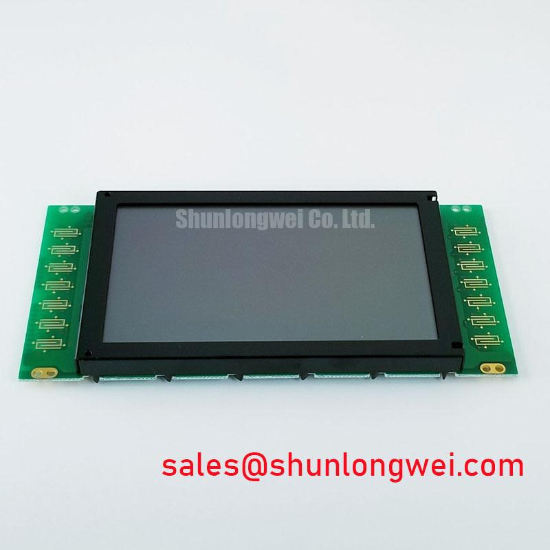
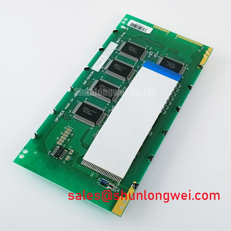
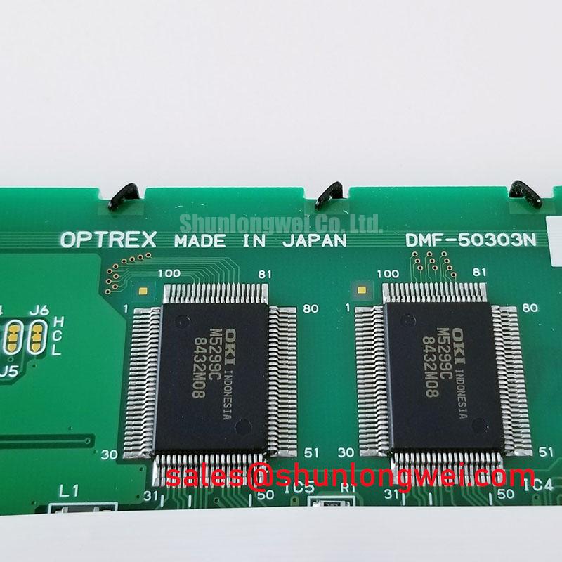
DMF 50303N Industrial TFT LCD Display Module
Before fitting the DMF 50303N, inspect the TFT LCD display module bezel, viewing surface, connector area, and perimeter sealing surfaces under clean lighting, then compare the original machine documentation with the replacement assembly before power is applied. This Kyocera OPTREX unit is identified as an Industrial Grade LCD/HMI Panel in a TFT LCD Display Module format. Required electrical supply, signal interface, backlight configuration, mechanical outline, and environmental limits must be verified from the original panel documentation and the equipment service record.
For equipment repair, the first objective is interchangeability at the assembled display level rather than a visual similarity check. Confirm the original cable routing, connector locking arrangement, mounting reference points, enclosure gasket contact, controller output format, and power sequencing behavior. An industrial TFT panel can present a stable image during a short bench test yet show intermittent artifacts after vibration, thermal cycling, or moisture exposure inside the machine enclosure.
| Item | Product Information |
|---|---|
| Model | DMF 50303N |
| Manufacturer | Kyocera / OPTREX |
| Product Category | Industrial Grade LCD/HMI Panel |
| Module Type | TFT LCD Display Module |
| Specification Status | Verify against applicable factory documentation |
High Humidity Storage Margins and Delamination Prevention Protocols
Humidity control begins before the panel enters the host enclosure. During service work, inspect the front gasket land and the rear chassis interface for trapped debris, deformation, incomplete compression, or evidence that a cable has prevented the bezel from seating evenly. These conditions can create a local moisture path or an uneven mechanical load that later appears as edge discoloration, optical nonuniformity, or intermittent display behavior.
The stated temperature and humidity figures often used in industrial environmental discussions, including 60°C / 90% RH storage screening and thermal exposure spanning minus 30°C to plus 85°C, are not confirmed factory ratings for DMF 50303N. They should be treated only as environmental assessment conditions that a system integrator may use when evaluating the original equipment enclosure, storage process, and maintenance procedure. The applicable product limits must come from the relevant Kyocera OPTREX documentation.
At low ambient temperature, liquid crystal response can become visibly slower. A delayed transition between gray levels can be mistaken for a controller fault, especially during a cold start. Begin diagnosis by allowing the machine and panel assembly to stabilize at its normal operating temperature, then compare the image against the known good signal path. If the effect changes with temperature, inspect enclosure sealing, local condensation control, cable strain, and controller timing before attributing the behavior to the panel itself.
Perimeter seal integrity is also affected by storage practice. Avoid placing an unprotected module directly onto a conductive or wet work surface. Keep its protective face material in place until the final fitting step, and do not use cleaning fluids that can migrate toward the bezel edge. Optical bonding, when specified for the complete equipment display assembly, can reduce air gaps and improve resistance to dust ingress, but it must not be assumed to be a feature of this individual model without supporting documentation.
Signal quality requires equal care when a display harness passes through a high noise cabinet. 100 Ω differential impedance with a tolerance of ±10% and a skew budget of 50 ps or less are general interface design considerations sometimes applied to high speed differential display paths, not official DMF 50303N requirements. The machine designer should validate the actual cable, connector, controller, and panel interface against the original electrical documentation.
Suppressing Pixel Jitter and Horizontal White Lines Induced by Adjacent 400V Motor Drives
When pixel jitter, short horizontal white bands, or momentary image instability appears only while a nearby motor drive is switching, inspect the display cable route before replacing the LCD module. Check whether the harness runs parallel to motor output conductors, passes through the same gland as power wiring, or has lost its original clamp and shield termination. These observations provide more useful evidence than a static screen test performed with the drive disabled.
A 360 degree shield termination at the intended chassis entry can be a Design Consideration where the original equipment cable construction and grounding architecture support it. Common mode ferrite suppression may also be evaluated when conducted or radiated interference is demonstrated. Neither measure should be added blindly. Cable shield treatment can alter the system return path, so the final arrangement should be verified with the machine operating under representative motor load conditions.
The nearby use of a 400 V variable frequency drive does not establish a particular electromagnetic compatibility limit or immunity rating for DMF 50303N. It identifies a possible interference source within an installation. Use a scope to compare display supply stability and signal behavior with the drive inactive and active, while following the equipment safety procedure. Check the grounding relationship between the panel chassis, HMI controller, drive enclosure, and vehicle frame where applicable.
For AGV and forklift telematics displays, vibration can turn an otherwise acceptable cable route into an intermittent connection. Inspect FPC or display harness bend points for unsupported flexing, sharp folds, pulled connector latches, and contact contamination. The flexible cable should follow the original bend path and be restrained so vehicle movement is not transmitted directly into the connector.
Published information about capacitor equivalent series resistance and ripple current can help technicians understand why aged power filtering within a host controller may contribute to supply disturbance under load. It does not identify a fault in the LCD by itself. For current rail investigation, engineers may also refer to ADI high precision current sense amplifiers when selecting suitable diagnostic methods for the surrounding power system.
⚠️ Maintenance Note: Inspect cooling air paths, cable clamps, and bezel gasket condition during scheduled machine maintenance before vibration or heat can turn a marginal display installation into an intermittent fault.
For a wider reference on display behavior, cabling, image artifacts, and industrial TFT selection factors, see The Ultimate Guide to Industrial TFT LCD Technology.
Solid State WLED Constant Current Driving, 1000:1 PWM Dimming and Flicker Suppression
The backlight type and electrical requirements of DMF 50303N must be confirmed from the original panel documentation. Do not assume that a replacement module uses WLED lighting, CCFL lighting, a particular dimming scheme, or a particular supply voltage. A correct mechanical fit does not establish backlight driver compatibility.
CCFL ignition figures such as 1500 to 1650 Vrms, LED dimming ratios such as 1000:1, and claimed brightness half life figures exceeding 50,000 hours are not official specifications supplied here for DMF 50303N. They must not be applied as model ratings. They are examples of system level topics that can be relevant only after the actual panel and inverter or LED driver documentation has been identified.
Where the original display system uses a constant current LED driver, the service technician should examine whether brightness instability follows supply load, PWM control activity, cable movement, or panel temperature. Audible noise can originate in the surrounding driver circuit, mounting hardware, or power conversion assembly rather than in the display glass. Record the operating condition that produces the symptom and compare it with the original controller configuration.
In cold warehouses or outdoor vehicle duty, slower gray transitions may be seen during the first period after startup. If the host assembly includes a heater strip or thermal controller, its implementation, control sequence, and safety limits are system determined. Verify that any thermal management hardware remains consistent with the original equipment design. Do not attach heaters, change controller settings, or bypass temperature protections without the system manufacturer’s documented procedure.
Long periods of static HMI content also deserve attention. Fixed icons, alarm banners, and status panels can make image retention more noticeable on some display technologies or at particular brightness and temperature conditions. Rotate noncritical content when the equipment software supports it, validate screen blanking behavior, and distinguish temporary image persistence from a signal or backlight issue through controlled observation.
Chassis M3 Fastener Torque Sizing to Eliminate Optical Mura Defects
Fit DMF 50303N to a clean, flat mounting surface and bring the bezel into contact progressively across the chassis rather than tightening one corner to its final load first. Uneven fastening can distort a display assembly and may create localized brightness variation, pressure marks, or dark field mura that is absent when the module is free on the bench.
The 0.35 to 0.45 N·m cross pattern M3 torque range is a general industry Design Consideration, not an official DMF 50303N torque specification. Use it only as a reference point when the host equipment drawing, fastener type, thread engagement, bezel design, and material stack have been reviewed. The equipment manufacturer’s mechanical drawing takes priority. If that document is unavailable, the responsible engineer should establish an appropriate process through controlled assembly evaluation rather than treating a generic torque value as mandatory.
Check that the enclosure opening does not impose an edge load on the active viewing region. The outer bezel envelope, gasket thickness, spacer arrangement, and rear support points must be matched to the original display assembly. A panel clamped against a warped surface can appear acceptable at installation but develop uneven optical behavior after vehicle shock or enclosure temperature change.
After mechanical installation, reconnect the original cable without twisting or forcing the connector. Confirm latch engagement, strain relief, and the specified cable bend direction. Differential pair routing principles remain relevant if the host uses a differential display interface: preserve the original controlled path, avoid unnecessary stubs, and verify actual signal margins during switching tests in the installed machine. This approach helps separate installation related artifacts from panel related concerns without assigning an unsupported single cause.