

Content last revised on October 9, 2026
High-Humidity Storage Margins and Delamination Prevention Protocols
| Product | NL12876BC26-22 |
|---|---|
| Manufacturer | NEC |
| Category | Industrial Grade LCD/HMI Panel |
| Display Technology | TFT-LCD Active Matrix Color Display Module |
| Specification Status | Decoded Baseline / Standard Form Factor |
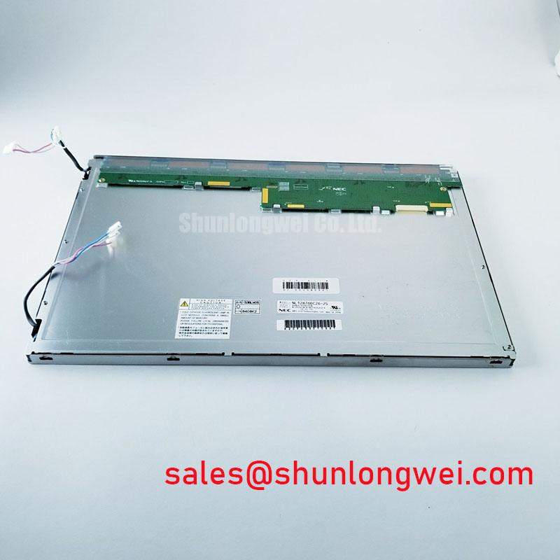
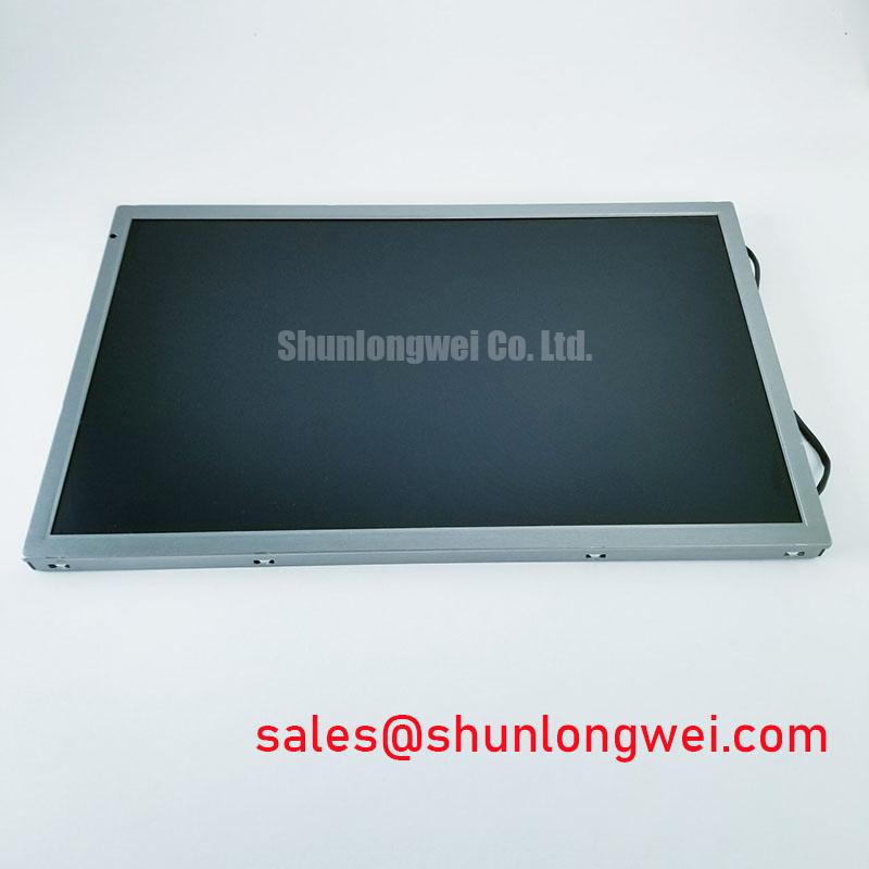
Inspect the display perimeter, connector area, and visible cell edges after humidity exposure before applying power to the NEC NL12876BC26-22. The supplied product information identifies this unit as a TFT-LCD active matrix color display module for industrial HMI integration, but it does not define a guaranteed humidity storage limit or a validated delamination profile. Storage and enclosure qualification therefore remain system-level design considerations.
For equipment exposed to temperature cycling between sub-zero conditions and elevated cabinet temperatures, allow the module to reach a stable temperature before functional testing. A cold liquid-crystal layer can respond more slowly, which may appear as gray-to-gray image lag during startup or rapid screen transitions. This visual behavior should be separated from signal timing faults by comparing the same image pattern at stabilized and cold conditions.
Perimeter seal stability is best evaluated through controlled environmental testing that reflects the final enclosure, bezel pressure, cable routing, and mounting method. Look for edge haze, localized contrast changes, bubbles, or visible separation after the test sequence. These observations are useful for locating mechanical or environmental stress, but they should not be interpreted as a manufacturer-rated failure threshold for this model.
Where the host system uses a differential display link, the PCB and cable design should preserve balanced routing, controlled impedance, and low skew across the complete signal path. A 100 Ω differential impedance with a ±10% design target and a skew budget of 50 ps or less may be used as an engineering evaluation reference for high-noise industrial layouts, subject to the actual interface specification and receiver requirements. The system designer should validate the final eye opening under the installed cable length, connector arrangement, and enclosure wiring.
Industrial display references can be reviewed through Industrial TFT Display Solutions and the NEC Display Solutions corporate resource. For a comparison path, engineers may also review the mechanical and interface requirements of NL10276AC30-53D without treating it as a direct substitute.
Eye-Diagram Voltage Margin and Differential Noise Floor Verification in High-Vibration Bays
Capture the display-link eye diagram at the receiving end of the installed cable rather than relying only on a bench connection. In an AGV or forklift telematics enclosure, vibration can change connector contact conditions and cable geometry while nearby variable-frequency motor drives can raise the common-mode noise floor. The result may appear as pixel jitter, intermittent horizontal bands, or unstable image data without proving a defect inside the LCD module.
A shielded FFC or LVDS cable should be assessed as part of the complete grounding arrangement. Check whether the shield termination, chassis bonding, connector shell, and signal reference follow the host equipment design. A shield that is mechanically present but poorly bonded can provide inconsistent noise performance. Common-mode ferrite components may be evaluated by the system designer when conducted interference is present, but their suitability depends on the data rate, common-mode spectrum, signal amplitude, and power sequencing.
For a suspected interface problem, compare the known-good signal path with the installed path under the same image pattern and motor operating condition. Observe differential amplitude, crossing symmetry, eye closure, and the timing relationship between clock and data lanes. This comparison is more useful than assigning a single fault cause to a noisy picture. It also helps distinguish cable movement, connector stress, grounding interaction, and source timing from a panel-side issue.
Backlight service work requires the display supplier documentation and the host driver specification to be considered together. If the host uses a constant-current LED backlight driver, examine current regulation, open-load response, short-circuit handling, thermal behavior, and diagnostic output. A stated figure such as 50,000 hours to 50% brightness is a commonly used industry life reference, not an automatic lifetime rating for the NL12876BC26-22 unless explicitly supported by the relevant manufacturer documentation. Record brightness against operating temperature and drive conditions when building a maintenance profile.
When the panel is evaluated for a rugged vehicle display, the mounting frame should prevent point loading around the glass and connector region. Vibration qualification should include the actual bezel, fasteners, cable bend path, and shock transfer through the vehicle structure. The Industrial Display & HMI Solutions reference provides a broader framework for reviewing enclosure, interface, and environmental integration questions.
Surface Anti-Glare and Anti-Reflective Etched Coating for High Ambient Readability
Evaluate the installed viewing angle and reflected-light pattern with the complete front bezel, cover window, and operator position in place. The supplied baseline for the NL12876BC26-22 identifies a TFT-LCD active matrix color display module, but it does not specify an AG coating, AR treatment, viewing cone, or sunlight contrast rating. Those optical characteristics should not be assigned to the model without the applicable optical datasheet.
In bright warehouse aisles or outdoor vehicle operation, readability is affected by the interaction between panel luminance, cover-window reflection, surface texture, ambient illumination, and displayed content. A matte surface can reduce mirror-like reflection but may also alter perceived sharpness. An AR treatment can reduce selected reflection components, while its performance depends on the optical stack and the incident light angle. These are system integration considerations rather than confirmed construction details for this unit.
TN, IPS, and MVA technologies can present different grayscale behavior and viewing-angle characteristics, but the NL12876BC26-22 listing supplied here does not identify the panel mode. Do not assume a symmetric viewing cone such as 85 degrees in every direction or a contrast ratio above 500:1 under 50,000 lux unless the original optical specification confirms it. Instead, test black level, grayscale separation, and text legibility from the actual driver or operator position.
For AGV and forklift telematics applications, inspect the panel through the final protective window rather than testing the bare module alone. Check glare at the normal viewing angle, at a shallow angle, and under direct overhead lighting. A camera-based measurement can supplement visual evaluation, but operator readability should remain part of the acceptance test because reflected highlights may obscure warning icons or small diagnostic text even when average luminance appears sufficient.
When an existing enclosure is reused, compare the opening, bezel overlap, connector clearance, and optical stack height before ordering a replacement. The standard-form-factor description is useful for initial sourcing, but it does not replace a mechanical drawing review. Designers should also verify that the mounting frame does not twist the glass during tightening or transfer vibration directly into the display edge.
Pro Tip: Keep high-speed differential pairs physically separated from backlight switching and motor-drive wiring, then verify pixel-clock stability at the panel connector with the final cable and grounding arrangement.
Single Vertical Hairline Defect and Sub-Pixel Column Driver Open-Circuit Localization
Display a full red field, followed by full green and full blue fields, before diagnosing a single vertical hairline. A line that remains fixed through all primary-color patterns deserves a different inspection path from a backlight shadow, while a line that changes with image content may require signal-path analysis. This three-pattern bench check is a practical screening method, not a model-specific failure threshold.
Use a low-angle flashlight from approximately 45 degrees to inspect the dark region around the line while the display is operating at a safe, stable condition. A shadow that follows the illumination path can point toward optical or backlight interaction, whereas a sharply fixed column boundary may justify inspection of the panel edge, connector seating, and driver region. Avoid pressing the glass or flexing the module during this test because mechanical force can create a temporary visual change that is difficult to reproduce.
COG-related or column-driver concerns should be localized by comparing the defect position across different refresh content, grayscale levels, and power cycles. A persistent line does not by itself prove a micro-fracture or open circuit. Check the source timing, data format, connector alignment, and cable retention before assigning the fault to the display cell or driver area.
Backlight control should be examined separately from pixel-data integrity. If the host system uses PWM dimming, evaluate the selected frequency, duty-cycle linearity, camera-visible flicker, audible behavior, and interaction with the constant-current driver. A frequency range of 200 Hz to 1 kHz can be used as a system evaluation window when required by the host design, but the correct operating point must follow the backlight driver and panel interface documentation.
Open-load and short-circuit protection belong to the external backlight driver unless the original module documentation assigns those functions to the display assembly. During fault testing, monitor driver status output, current behavior, restart timing, and panel temperature without repeatedly reconnecting a live cable. Safety Interlock Note: Disconnect power before removing or inserting the display cable to reduce the risk of connector and interface damage.
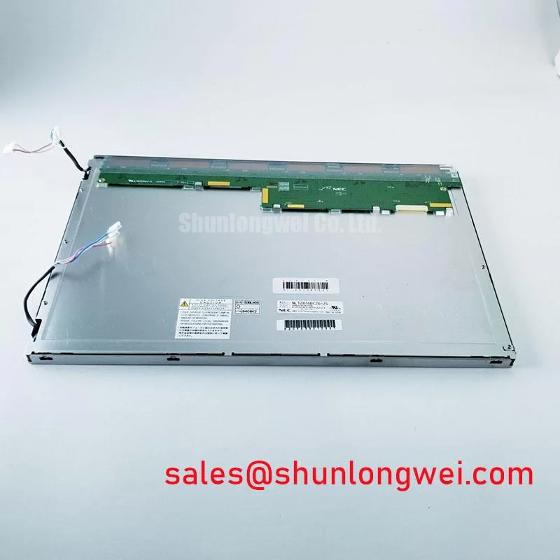
For procurement or field replacement, match the NEC brand, NL12876BC26-22 model designation, TFT-LCD active matrix color technology, mechanical envelope, connector orientation, and host timing requirements as one compatibility set. A category match alone is insufficient when the enclosure opening, image format, cable path, or backlight control differs.