

Content last revised on June 26, 2026
DMF-50773-NF-FW: A Robust 5.7" QVGA Display for High-Clarity Industrial HMIs
Engineering-Grade Insights for OEM Design and Procurement
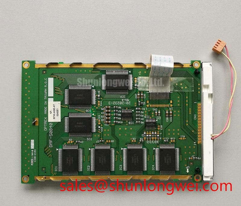
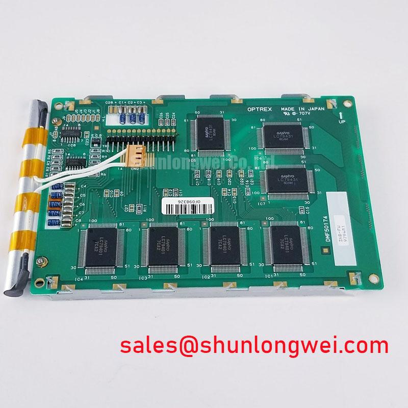
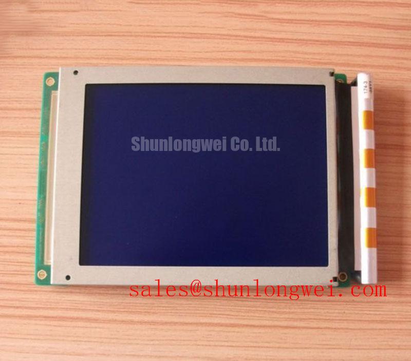
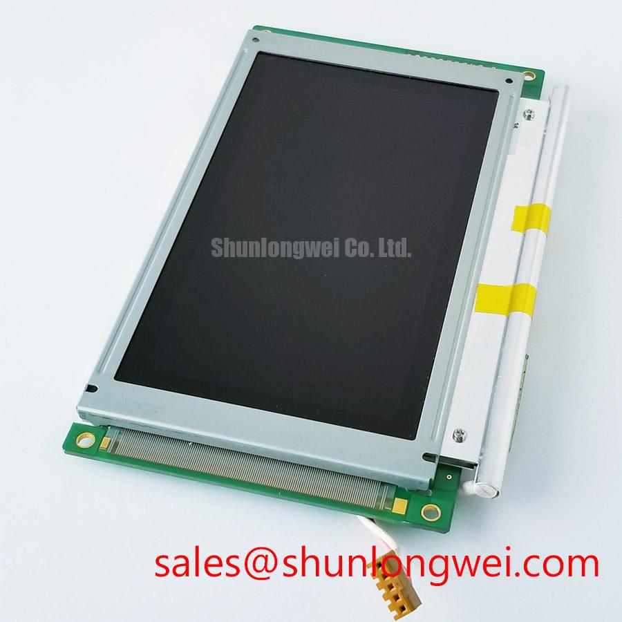
The DMF-50773-NF-FW is a rugged 5.7-inch monochrome display engineered for mission-critical clarity and reliability in demanding industrial environments. Featuring a specification of 320 x 240 QVGA | 250:1 Contrast Ratio (Typ.) | -20°C to 70°C Operating Temperature, it delivers two primary engineering benefits: excellent readability in diverse lighting and simplified system integration. This module is a prime candidate for retrofitting legacy systems due to its standard QVGA resolution and parallel data interface, ensuring broad compatibility. For industrial controls or medical devices requiring a highly reliable, high-contrast display that operates in extreme temperatures, the DMF-50773-NF-FW offers a proven solution.
Key Parameter Overview
Decoding the Specs for Environmental and Visual Reliability
The technical specifications of the DMF-50773-NF-FW are optimized for long-term performance in applications where operational uptime and data legibility are paramount. The following table groups key parameters by function, providing a clear overview for system architects and design engineers.
| Feature | Specification | Engineering Value |
|---|---|---|
| Display Characteristics | ||
| Display Type | F-STN LCD, Monochrome | Provides high-contrast, crisp text and graphics ideal for data-centric interfaces. |
| Resolution | 320 x 240 (QVGA) | Industry-standard resolution ensures compatibility with a wide range of microcontrollers and legacy software. |
| Active Area | 115.18(W) x 86.38(H) mm | Offers a substantial viewing area for its 5.7-inch diagonal size. |
| Contrast Ratio | 250:1 (Typical) | Delivers exceptional clarity and readability, reducing operator eye strain and potential for errors. |
| Environmental & Electrical | ||
| Operating Temperature | -20°C to +70°C | Guarantees stable operation in unconditioned indoor and protected outdoor environments. |
| Storage Temperature | -30°C to +80°C | Ensures module integrity during transport and storage in extreme climates. |
| Backlight System | 1 x CCFL with Inverter | An integrated backlight solution simplifies power supply design and system integration. |
| Interface | Parallel Data (8-bit) | A straightforward and widely supported interface for direct connection to system controllers. |
Note: The parameters listed above are for reference. For complete electrical and mechanical specifications, please refer to the official documentation.
Download the DMF-50773-NF-FW datasheet for detailed specifications and performance curves.
Application Scenarios & Value
System-Level Benefits in Harsh Operating Environments
The DMF-50773-NF-FW is engineered for applications where environmental conditions are a primary design constraint. Its robust construction and wide operating temperature range make it a premier choice for Human-Machine Interfaces (HMIs) in challenging settings.
Consider a PLC-based control panel on a factory floor that is not climate-controlled. The ambient temperature can plummet below freezing on a winter morning and soar during summer operations. The DMF-50773-NF-FW's ability to operate flawlessly from -20°C to +70°C ensures the HMI remains a reliable point of control, preventing costly downtime. The high 250:1 contrast ratio is also critical in this scenario. Think of this contrast as the difference between writing in faint grey pencil on a grey page versus sharp black ink on a white page. For an operator under shifting factory lighting, this high contrast ensures critical alerts and process data "pop" from the screen, minimizing the chance of misinterpretation and improving operational safety. What is the key benefit of the DMF-50773-NF-FW's temperature range? It ensures operational reliability in uncontrolled industrial and field environments.
While this model is optimized for monochrome industrial applications, systems requiring color visualization and similar durability may consider models like the KCG057QV1DB-G000.
Application Vignette
Upgrading Legacy Test and Measurement Equipment for Field Reliability
A common engineering challenge involves upgrading legacy field equipment where a full redesign is not feasible. An OEM producing portable spectrum analyzers faces this issue: their existing displays are failing due to age and temperature extremes encountered by field technicians. They require a replacement that fits the existing mechanical cutout, uses a parallel interface, and offers superior readability and durability.
The DMF-50773-NF-FW presents an optimal solution. Its standard 5.7-inch form factor and QVGA resolution allow for direct mechanical and electrical integration, preserving the existing product architecture. The critical advantage is the immediate upgrade in field reliability. Its broad operating temperature range is akin to equipping a vehicle with all-season tires instead of summer tires; it is engineered to perform reliably from a frigid winter start to the peak heat of a summer day, eliminating the display as a point of failure. This enhancement to the Test and Measurement Equipment's robustness significantly reduces warranty claims and improves customer satisfaction, directly impacting the OEM's bottom line by extending the product's service life.
Frequently Asked Questions (FAQ)
How does the specified -20°C to 70°C operating temperature range benefit system design in industrial automation?
This wide temperature range allows the display to be deployed in non-climate-controlled environments, such as factory floors, outdoor-covered terminals, or vehicle cabins, without requiring costly auxiliary heating or cooling systems. This simplifies the overall thermal management design, reduces system complexity, and lowers the total cost of ownership.
What is the significance of the 250:1 contrast ratio for an operator interface?
A high contrast ratio is crucial for immediate and accurate data interpretation. In an industrial HMI, it ensures that text, numbers, and status indicators are sharply defined against the background, even under poor ambient lighting or from an off-angle view. Why is a 250:1 contrast ratio important? It provides excellent screen clarity, reducing operator reading errors and improving safety.
Is the DMF-50773-NF-FW suitable as a drop-in replacement for older QVGA displays?
Yes, its industry-standard 320x240 resolution, 5.7-inch diagonal size, and parallel data interface make it a strong candidate for replacing obsolete or end-of-life monochrome displays in existing designs. This allows for system life extension and service repairs with minimal to no hardware or software re-engineering, protecting the initial investment in the equipment.
Request for Quotation
To evaluate the DMF-50773-NF-FW for your design or to inquire about volume pricing and availability, please contact our technical sales team. We provide engineering support to help you verify compatibility and streamline your procurement process for your next project.