

Content last revised on September 10, 2026
Industrial Bezel Mechanical Envelope Tolerances & Mounting Screw Torque Optimization
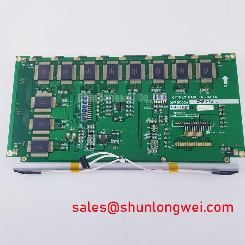
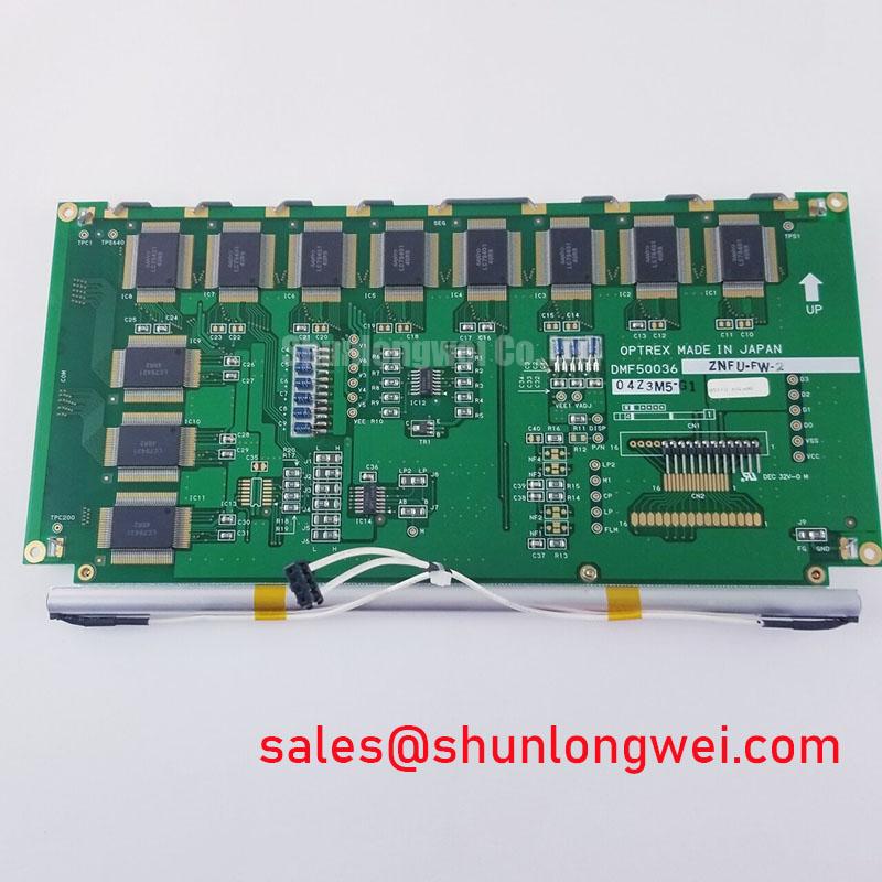
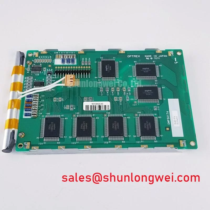
Inspect the bezel face, mounting flange, connector area, and visible display surface before installation, then compare the replacement assembly with the removed unit for mechanical alignment and interface compatibility. DMF-50174 is identified as a Kyocera / OPTREX TFT-LCD Display Module for industrial LCD and HMI applications, with an official factory specification status provided for the product record.
The available factory information confirms the product category, manufacturer, and TFT-LCD module construction, but it does not establish a complete mechanical drawing, active-area dimension, mounting-hole pattern, connector pinout, display resolution, viewing angle, interface type, backlight architecture, or operating-temperature rating. The system integrator should verify those items against the original panel documentation before approving a replacement for a railway passenger information system, cab signalling display, or industrial operator terminal.
Mechanical installation should begin with the chassis opening rather than the fasteners. Check the bezel aperture, corner radii, panel depth, connector clearance, cable bend path, and compression of any dust seal or gasket. A display that fits the opening can still experience uneven frame loading if the enclosure is distorted or if the gasket is thicker than the original part. Localized pressure may appear later as non-uniform brightness, edge shading, or dark-field mura. These symptoms require inspection of the complete mechanical stack rather than an immediate assumption that the LCD cell itself is defective.
The requested cross-pattern M3 torque range of 0.35 to 0.45 N·m should be treated as an engineering installation recommendation for a compatible enclosure, not as a confirmed factory limit for DMF-50174. The actual value must be checked against the chassis material, screw grade, insert design, gasket compression requirement, and the display manufacturer’s mechanical drawing. Tighten progressively in a diagonal sequence so the bezel load is distributed evenly. A torque driver and a final visual inspection of the panel surface are preferable to relying on hand feel.
For cold installations, designers should verify the panel’s specified operating range and the enclosure’s heater control strategy from the original documentation. Liquid-crystal viscosity can increase at low temperature, extending gray-to-gray transitions and making moving text appear less responsive. This is a system-level behavior that depends on the panel construction, drive timing, backlight temperature, and image content. It should be assessed with the intended controller and a representative test pattern rather than inferred from the model number.
A heater strip may be considered where the equipment environment requires rapid recovery from sub-zero conditions, but its location and control method must be selected to avoid creating a thermal gradient across the display. The sensor should measure the relevant panel or bezel temperature, not only the cabinet air. Condensation control also requires attention during warm-up, because a cold display moved into humid air can collect moisture before the enclosure reaches thermal equilibrium.
Diffuser Film & Prism Sheet Thermal Buckling Prevention under Continuous Full-Duty Operation
Continuous full-duty operation calls for an inspection of the complete thermal path around the module. Confirm that the rear cover, heat spreader surfaces, ventilation openings, and nearby power electronics do not direct a concentrated heat source toward one edge of the display. The available factory data for DMF-50174 does not confirm the diffuser film, prism sheet, LED arrangement, PMMA light-guide construction, L70 rating, or B50 service-life value. Those characteristics should not be assigned to this model without the applicable Kyocera or OPTREX documentation.
An aluminum edge rail or heat-spreading structure can be evaluated as an enclosure-level design measure when temperature mapping identifies a local hot spot. It should not press directly on the active display area or create a rigid point load on the optical stack. Thermal expansion between the chassis, bezel, and display frame must remain mechanically compatible throughout the specified operating range. The correct solution depends on the enclosure geometry and measured thermal distribution, so engineers should validate it using thermocouples or an equivalent temperature-mapping method during sustained operation.
Optical non-uniformity should be checked after the panel reaches a stable temperature. Use dark, mid-gray, white, and text-rich patterns while viewing the display from the intended service position. Edge brightening, localized dark regions, or changes that follow the fastening points may indicate mechanical stress, optical stack movement, cable interference, or thermal imbalance. This diagnostic approach is more reliable than assigning a single cause to a visible mura pattern.
The display interface also requires an electrical compatibility review. The product record supplied for DMF-50174 does not specify LVDS, eDP, RGB, or another signal format, and it does not publish a differential impedance or skew requirement. If the original system uses a high-speed differential link, the integrator should obtain the panel timing and interface documentation, preserve the original routing topology, and verify signal quality at the receiver. Differential pair matching, return-path continuity, shielding, and connector grounding should be evaluated together in the presence of factory switching noise.
A commonly used 100 Ω ± 10% differential target may apply to some display links, but it is a general interface design consideration rather than an official DMF-50174 specification. The same distinction applies to a proposed skew budget of 50 ps or less. Such values must come from the controller, cable, receiver, and panel interface requirements. Engineers should confirm eye opening, common-mode behavior, and error performance with an oscilloscope or suitable compliance fixture under the actual enclosure and cable arrangement.
Long-term static graphics also deserve an operational review. A railway route map, fixed status bar, or diagnostic screen can remain unchanged for extended periods. Whether image retention, temporary persistence, or permanent degradation is possible depends on the LCD technology, drive method, temperature, luminance setting, and duty profile. The system owner should use the panel documentation and controlled endurance testing to define screen-saver, pixel-shift, brightness, and content-rotation policies instead of applying an assumed lifetime figure.
For broader enclosure, sealing, thermal, and HMI integration considerations, engineers may consult Industrial Display & HMI Solutions as a related technical reference. Kyocera also publishes information on silicon nitride substrates for power modules; that material is relevant to power semiconductor packaging and should not be interpreted as a specification for this LCD module.
High-Humidity Storage Margins (60°C / 90% RH) & Delamination Prevention Protocols
Before placing DMF-50174 into a humid equipment enclosure, inspect the gasket contact surface, cable entry points, rear cover, and any bonding interface visible from the outside. The supplied product information confirms a TFT-LCD display module but does not provide a humidity-storage qualification, condensation rating, adhesive system, perimeter seal construction, optical-bonding specification, or thermal-cycle certification. The values 60°C and 90% RH should therefore be used only as proposed environmental test conditions when they are required by the equipment specification, not as an automatic rating for the module.
Humidity protection begins with enclosure design. A gasket should sit on a clean, continuous land without folds, gaps, sharp transitions, or excessive compression at one corner. The rear cover should be checked for warpage after fastening, because a small gap along the display perimeter can allow humid air to reach the internal surfaces during temperature cycling. Cable glands and venting components should be selected for the equipment’s environmental requirement, with pressure equalization considered where repeated heating and cooling could draw moist air through an imperfect seal.
Storage and installation procedures should distinguish between condensation and general humidity exposure. A module removed from a cold storage area should be allowed to reach a controlled temperature before power is applied. If moisture is suspected, inspect the connector and frame perimeter and follow the equipment manufacturer’s approved drying procedure. Do not use uncontrolled hot air on the display surface, adhesive joints, or flexible cable.
Low-temperature performance should be evaluated with the intended controller and image sequence. As the liquid crystal responds more slowly in cold conditions, gray-to-gray lag may become visible in scrolling characters, moving symbols, or rapidly changing alarm pages. The proper mitigation may involve a controlled warm-up period, an adjusted content policy, or a display timing strategy approved by the original system designer. It should not be assumed that a generic drive adjustment will be valid for this model.
Backlight control also requires documentation. The supplied factory parameters do not identify whether DMF-50174 uses LED or another backlight arrangement, and they do not publish a PWM frequency, duty-cycle linearity specification, dimming ratio, or acoustic behavior. The integrator should verify the required backlight supply and control method from the original panel documentation. If PWM is used, the selected frequency and duty behavior should be assessed for visible flicker, camera interaction, text readability, and compatibility with the backlight driver.
Power sequencing is equally important during field replacement. Confirm the order and timing of logic supply, display enable, video data, and backlight enable from the controller and panel documents. A white screen, unstable image, or residual image after shutdown can involve an incorrect enable sequence, an incompatible controller state, cable contact, or residual energy in the backlight circuit. Capture the relevant supply and control signals during startup and shutdown, comparing them with a known-good assembly where available.
⚠️ Maintenance Note: Inspect the cooling airflow path and display gasket condition during scheduled cabinet service, and disconnect power before removing the display cable.
Backlight High-Voltage Resonant Inverter Striking Voltage & Ignition Debugging
Do not connect a replacement backlight or inverter based only on connector appearance. The factory information supplied for DMF-50174 does not confirm CCFL tubes, dual-channel inverter architecture, cold-ignition voltage, LED driver topology, PWM dimming range, or backlight connector assignment. The system integrator should verify the original backlight technology, voltage, current, enable logic, dimming method, and protection behavior before energizing the assembly.
For an original CCFL system, a high-voltage ignition event can involve a resonant inverter, lamp characteristics, cable capacitance, insulation, and ambient temperature. The proposed 1500 to 1650 Vrms striking range is not an official DMF-50174 specification in the supplied data. It should not be used as a test target without the applicable inverter and panel documentation. High-voltage measurements require equipment rated for the circuit and a procedure that protects the operator from exposed conductors and stored charge.
When an older display has uneven illumination, delayed ignition, intermittent shutdown, or audible noise, examine the inverter supply, enable signal, lamp cable routing, connector seating, and chassis bonding as a complete circuit. A single symptom can result from several conditions, including protection activation, cable insulation stress, supply instability, or a mismatch between the inverter and lamp load. Compare both channels where the design provides two channels, but avoid swapping connections unless the original wiring and protection scheme explicitly permit it.
If the equipment has been converted to an LED backlight, the LED driver must be treated as a system-specific assembly. The supplied data does not confirm a constant-current driver, a 1000:1 PWM dimming capability, or a particular duty-cycle response for this model. Engineers should verify current regulation, enable polarity, fault handling, startup behavior, and thermal performance using the original conversion documentation. A driver that lights the panel is not automatically electrically or optically compatible.
Acoustic buzz should be investigated with the enclosure assembled as it operates in service. Possible contributors include magnetics, mounting resonance, PWM interaction, loose covers, or a control loop operating outside its intended condition. Use a controlled change at one time, monitor the backlight current and supply waveform, and confirm that any adjustment remains within the driver and panel documentation. Do not claim a guaranteed half-life, MTBF, or service interval for DMF-50174 because no authoritative lifetime source has been provided for those values.
For railway passenger information displays and cab signalling terminals, final acceptance should include connector retention, boot behavior, readable text at the intended viewing angle, cold-start response, humidity recovery, enclosure sealing, and safe shutdown. The display should be approved only after its mechanical, electrical, optical, and environmental interfaces have been checked against the original equipment requirements.