Content last revised on October 14, 2026
MV215FHM-N50 Replacement Evaluation
- Disconnect equipment power before checking the MV215FHM-N50 label, cable orientation, connector latch engagement, and contact condition.
- Compare the controller’s connector drawing, supply requirements, and startup sequence with the panel documentation before connecting a replacement.
- Inspect mounting clearances, cable routing, and chassis contact points for pressure that could distort the display frame.
- Record whether the reported fault affects illumination, image content, viewing direction, or a fixed screen location before changing hardware.
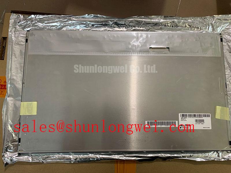
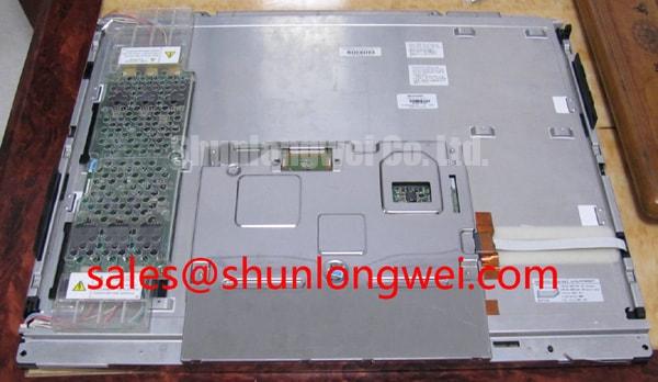
The BOE MV215FHM-N50 is a TFT-LCD active-matrix color display module for LCD/HMI integration evaluation. Replacement assessment should start with the complete model designation rather than enclosure appearance: mechanical fit, electrical compatibility, and image timing are separate acceptance checks.
| Product identity | Specification baseline |
|---|---|
| Model | MV215FHM-N50 |
| Manufacturer | BOE |
| Display construction | TFT-LCD active-matrix color display module |
| Integration category | LCD display / HMI panel evaluation |
| Electrical, optical, and mechanical acceptance data | Consult Datasheet: supply voltage, connector pinout, resolution, interface, dimensions, viewing characteristics, backlight requirements, and temperature limits |
Grayscale Inversion Mitigation & Optimal Viewing Direction Alignment
Display a grayscale ramp and inspect it from the intended operator position before approving the enclosure opening. Design Consideration: dark tones merging, reversing, or changing disproportionately with viewing angle can compromise alarm visibility even when text remains readable directly in front of the screen. Record the direction of the change with the display mounted in its intended orientation.
Normally white TN behavior is a comparison topic, not an established specification for this model. TN, IPS, and MVA describe different electro-optical operating approaches; a symmetrical viewing cone must not be assigned to the MV215FHM-N50 without its optical specification. Assess contrast and grayscale separately, since a readable white background does not establish acceptable shadow detail.
Surface reflections require a different check. Inspect the assembled display under representative overhead lighting, including any protective window. An anti-glare surface can redistribute reflected light, but it does not eliminate reflections or establish outdoor readability. Surface treatment should be identified from the panel specification rather than inferred from a photograph. The Winstar Industrial TFT-LCD and OLED Display Modules resource provides broader display-selection context, not BOE-specific performance evidence.
For a factory automation machine-tool HMI operator terminal, compatibility evaluation should include the normal standing position and enclosure tilt. When comparing the MV215FHM-N50 with another catalog item such as LQ10D41, compare actual drawings and interface requirements; a shared LCD category does not establish matching size, resolution, or interchangeability.
Backlight Constant-Current Driving, PWM Dimming & Flicker Suppression
Separate backlight-control measurements from image-interface measurements when brightness varies or the screen intermittently goes dark. Design Consideration: in an LED-backlit assembly, compare driver enable, dimming commands, and illumination behavior at the same operating point. A changing image and changing illumination are different observations and should not be treated as interchangeable fault evidence.
Constant-current regulation controls LED operating current, while PWM dimming changes illumination duty cycle. Neither a dimming ratio nor flicker performance follows from the panel model name. Evaluate the complete controller, driver, and display combination across the brightness settings actually used. Audible noise should be localized to its physical source rather than attributed automatically to the panel.
During integration, designers should check that panel power, image data, and backlight enable follow the documented sequence. Compare startup and shutdown waveforms with controller behavior when investigating white-screen events or residual images. Avoid changing delays blindly: an incorrect supply transition, absent image data, or controller configuration issue can produce overlapping symptoms.
For an LVDS-based controller, verify connector assignment, lane mapping, and the applicable JEIDA or VESA format before interpreting unusual colors as panel damage; first establish that the panel uses that interface. Pro Tip: As an Engineering Recommendation, preserve differential-pair symmetry through cable transitions and validate timing at the receiver before accepting a replacement cable. Backlight service-life assessment should use the applicable manufacturer test conditions; brightness maintenance and MTBF are different measures.
Optical-Layer Thermal Buckling Prevention under Continuous Full-Duty Operation
Inspect brightness uniformity after the assembled enclosure reaches a stable operating temperature, then compare it with the cold-start image. Design Consideration: a shadow that develops during warm-up warrants checks of frame loading, local temperature gradients, and enclosure restraint before assigning an internal optical-layer failure. The materials and arrangement inside this model should not be inferred from generic LCD construction.
Evaluate chassis heat paths without using mounting force to flatten the display. Heat-spreading provisions should accommodate the actual contact surfaces and available clearance; their dimensions belong to the enclosure’s thermal design. Leave the frame free of unintended point loads, and check whether cable retention transfers force into the connector during thermal expansion or vibration.
Flexible-cable reliability depends on routing as well as connection quality. Avoid concentrating movement at a crease or connector exit, and assess strain relief through the equipment’s expected service motions. A latch that closes successfully does not establish cable fatigue life. Likewise, optical bonding requires a separately qualified material and assembly process; it does not by itself establish moisture protection or enclosure sealing.
At low temperature, liquid-crystal response can slow, making moving edges appear smeared even when a static image remains correct. Compare behavior only within the documented operating range rather than assuming a wide-temperature rating. Heater arrangements are system-level options, not an established feature of this panel. The The Ultimate Guide to Industrial TFT LCD Technology provides supporting context for separating integration effects from component specifications.
Single Vertical Hairline Defect Investigation
Display solid red, green, and blue images in sequence and record whether the vertical line remains at the same physical column. Follow with neutral gray and a moving pattern to distinguish a stationary defect from content-dependent artifacts. Design Consideration: persistence across patterns narrows the investigation but does not independently prove an open column driver.
Compare the controller output with a known-good compatible signal path, then inspect accessible cable connections with power removed. A faint image visible under oblique external illumination can help separate missing illumination from missing image content, but it does not identify the failed backlight component. Avoid pressing the glass or bonded edges to provoke a response.
If a fixed line remains after controller and cable checks, document its position, color dependence, and temperature behavior for panel-level evaluation. Do not infer an internal bond fracture from appearance alone. For retained static graphics, compare a neutral test image after changing content; distinguish temporary image persistence from a persistent column defect before deciding which assembly requires replacement.