Content last revised on October 14, 2026
LM190E08-TLB4 Identification and Installation Checks
- Disconnect equipment power, discharge stored energy, and inspect the LM190E08-TLB4 connector contacts and cable retention before removing the display.
- Record the complete panel designation, controller configuration, and backlight connections before disturbing the existing installation.
- Compare mounting positions, bezel clearance, and cable exit direction with the replacement assembly; check that brackets do not load the display surface.
- Inspect the chassis bonding path and separate display wiring from power switching conductors before investigating intermittent image noise.
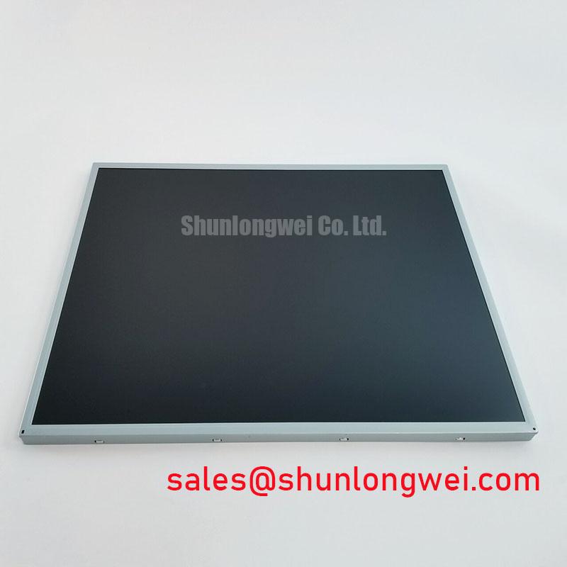
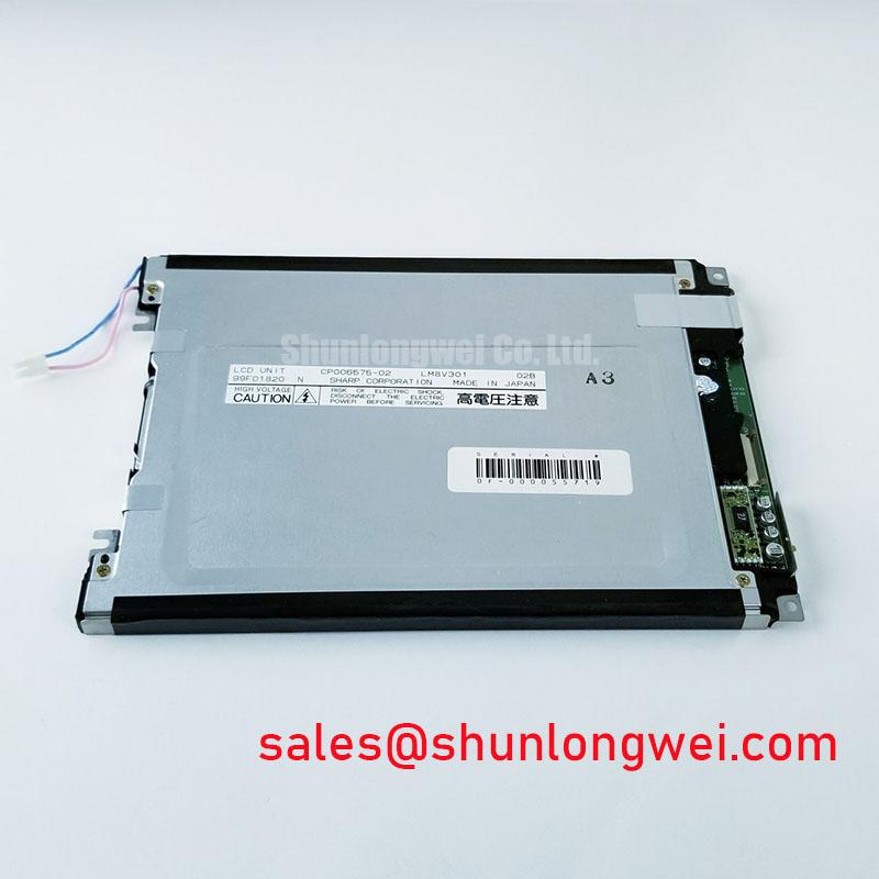
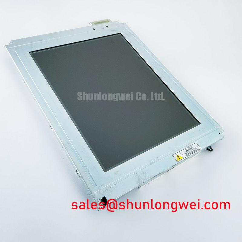
The LM190E08-TLB4 from LG Display is a TFT-LCD active matrix color display module for LCD/HMI integration assessment. Replacement suitability depends on the complete mechanical, electrical, and controller configuration, rather than the model family alone. The identification card below separates supplied product information from specifications requiring the model-specific datasheet.
| Identification item | Product information |
|---|---|
| Model | LM190E08-TLB4 |
| Manufacturer | LG Display |
| Product category | LCD display / industrial HMI panel integration |
| Module construction | TFT-LCD active matrix color display module |
| Electrical, optical, and mechanical ratings | Consult Datasheet: resolution, dimensions, supply voltage, connector assignment, backlight configuration, timing, and operating temperature |
Radiated Emissions Assessment (CISPR Class A/B) & Backplate Bonding
Trace the display cable shield termination and backplate bonding path when horizontal noise bands or pixel instability appear during nearby drive switching. As a Design Consideration, compare image behavior with the switching equipment inactive and active while keeping the displayed pattern unchanged. This comparison helps distinguish interference correlated with switching activity from persistent controller, connector, or panel faults.
Grounding topology should follow the equipment EMC architecture. A star connection and distributed chassis bonds serve different frequency-dependent purposes; neither automatically establishes CISPR compliance. Where a shielded display cable is specified, assess shield continuity and its chassis termination without extending the connection through an unnecessarily long conductor. Circumferential shield termination can be evaluated where the connector and enclosure support it. Common-mode suppression components require system-level testing rather than automatic inclusion.
Check backplate contact surfaces, bonding hardware, and paint beneath intended conductive interfaces. Maintain protective bonding independently of any experimental signal-ground changes. Radiated emissions classification belongs to the completed equipment and its applicable test configuration, not to the LM190E08-TLB4 alone.
For general display technology context, Tianma NLT Industrial TFT-LCD Display Technologies provides an industry reference; it does not establish LG Display model-specific ratings. Record the cable routing and enclosure configuration used during equipment testing so that subsequent service work preserves the evaluated arrangement.
Backlight Driver Compatibility, PWM Dimming & Flicker Suppression
Identify the installed backlight circuit and its control connections before connecting a replacement driver. The backlight subsystem must be matched to the panel documentation; a constant-current WLED driver is not an interchangeable substitute for a different backlight architecture. Connector appearance alone cannot establish compatibility.
As a Design Consideration, evaluate brightness control across the equipment’s intended adjustment range while observing both the light output and driver operation. Check whether the brightness command produces a smooth, repeatable response, particularly near the lowest usable setting. PWM frequency, minimum pulse behavior, and dimming range are determined by the compatible driver and system requirements, not by a generic dimming prescription.
If flicker or acoustic noise changes with brightness, correlate the symptom with the dimming waveform and supply behavior. These observations can help separate control instability from mechanical vibration or power conversion effects, but do not establish a single cause. Inspect connector seating and compare results with a known-good assembly under equivalent conditions.
Published dimming ratios, ignition voltages, or lifetime figures from other displays must not be transferred to this model. Backlight lumen maintenance and MTBF describe different reliability characteristics. The Winstar Industrial TFT-LCD and OLED Display Modules reference offers broader display context, not evidence of an LM190E08-TLB4 backlight specification.
Temperature Operational Margin & Low-Temperature Liquid Crystal Response
Evaluate image response at the equipment’s intended temperatures using moving patterns and representative interface transitions. As a Design Consideration, liquid crystal response generally slows as temperature falls, potentially increasing visible transition lag. Judge readability separately from electrical synchronization: a stable image can still update too slowly for the application.
Thermal assessment should stay within the documented panel limits and consider the temperature inside the enclosure, not just the room surrounding it. Observe warm-up behavior, brightness uniformity, and recovery after temperature changes. These measurements support an integration decision without assigning an unsupported wide-temperature rating or predicting operating life.
Optical bonding is an integration process, not an established feature of this module. If a cover lens is proposed, evaluate adhesive compatibility, thermal expansion, optical distortion, and rework requirements with the assembly supplier. Bonding can change internal reflections, but it does not independently establish a moisture-tight or dust-tight enclosure. Check bezel compression and bracket clearance so that enclosure loads are not transferred to the active display area.
For persistent HMI graphics, assess image retention using the actual interface layout and representative operating conditions. Screen changes or idle-screen behavior may be evaluated as system-level mitigation, without implying a guaranteed prevention method. The Industrial Display & HMI Solutions guide provides broader environmental integration context for enclosure and validation planning.
VESA vs. JEIDA Data Mapping Alignment & Even/Odd Channel Signal Integrity
Match the controller output to the panel’s documented interface, connector assignment, and data mapping before applying display signals. For an LVDS implementation, VESA/JEIDA alignment, color depth, channel allocation, and clock relationship must agree at both ends. Color errors or alternating-column artifacts can justify checking those settings, but are not conclusive evidence of a mapping fault.
Design Consideration: preserve differential-pair symmetry and continuous return paths to limit timing imbalance, then validate signal quality at the receiving interface. Avoid selecting impedance or skew limits from an unrelated panel. Cable construction, controller output characteristics, connector discontinuities, and the receiving interface together determine the appropriate validation conditions.
Review the controller’s power sequence against the panel requirements, including logic supply establishment, signal enable, backlight enable, and shutdown behavior. During white-screen or shutdown-afterimage investigation, capture the relevant rails and enables through startup and power removal. A static voltage measurement alone cannot show sequencing errors or residual powering through signal connections.
When evaluating LM201W01-SLA1 alongside this model, compare resolution, outline, mounting, interface, and backlight requirements rather than treating it as a direct substitute. Railway passenger information systems and cab signalling displays are potential compatibility assessments only; equipment-specific environmental and functional requirements remain part of that assessment. After configuration changes, test gradients, color patterns, and motion to check mapping, channel alignment, and transition behavior independently.