


Content last revised on September 29, 2026
Temperature Margin and Cold LCD Response
Run a full-screen gray transition test at the equipment’s lowest expected ambient temperature, then compare response with the same panel at room temperature. A slower transition can make moving graphics or changing readouts appear to trail, even when the input image is stable. As a Design Consideration, liquid-crystal response can slow in cold conditions; a satisfactory room-temperature image alone does not establish suitability for a cold installation.
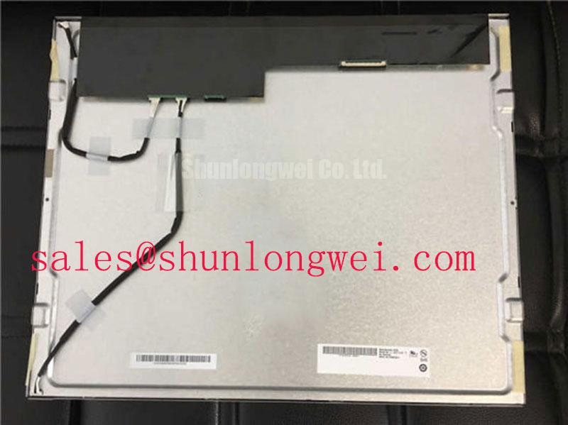
For G190EAN01-5, treat the permitted operating-temperature range, storage limits, response-time conditions, and any warm-up requirement as values to obtain from the applicable AUO revision before approving the installation. No temperature limit or response-time figure is established by the supplied factory specification facts. Record the panel temperature and displayed test pattern together: a report of “slow at startup” is difficult to act on without knowing whether the image improves as the enclosure warms.
Inspect the display perimeter and the host enclosure gasket separately. A displaced or compressed gasket can create an environmental entry path without indicating a defect in the LCD module. Condensation is another system-level concern when a cold assembly enters warm, humid air. The integrator should evaluate enclosure sealing, airflow, and any temperature-control arrangement against the actual duty cycle rather than assume that an industrial-grade designation makes the complete HMI resistant to moisture.
Watch the image during a controlled temperature change for persistent edge discoloration, pressure marks, or uneven brightness. Photograph any change at a fixed camera position and repeat the observation after the assembly returns to a stable temperature. This separates a repeatable environmental symptom from a viewing-angle effect or a mark on the cover window. Backlight aging or brightness retention cannot be assigned a service-life figure for this model from the supplied facts; establish a measured brightness baseline if the maintenance program needs one.
Ambient Readability and Surface Glare
Move a work light across the installed viewing window while displaying a mid-gray field and a high-contrast text screen; note whether reflections obscure information or whether the image itself changes with viewing position. These are different faults. Glare may originate at the enclosure window, the panel surface, or both, while a contrast shift seen from an angle may be characteristic of the LCD optical mode.
Do not specify an anti-glare etch, anti-reflective coating, TN mode, IPS mode, MVA mode, or a particular viewing cone for G190EAN01-5 without the matching AUO documentation. The supplied factory facts identify a TFT-LCD active-matrix color module, not its surface treatment or optical-mode details. For an equipment comparison, observe the installed assembly from the operator’s normal positions with representative screen content. The general explanation of LCD viewing-angle characteristics helps distinguish angular contrast changes from a defective image source; it does not establish this panel’s viewing-angle rating.
Check the outer window for haze, cleaning residue, scratches, and an air gap that reflects overhead lighting. These checks matter before changing the LCD: replacing a sound panel will not remove a reflection produced by the cabinet glazing. As a Design Consideration, compare readability under the brightest expected ambient condition while keeping the cabinet’s sealing method and operator position unchanged. An outdoor-facing marine radar or navigation bridge console is one possible compatibility evaluation, subject to verified panel ratings and the protective design of the complete console; the panel’s industrial category alone does not establish salt-mist or sunlight performance.
If the screen dims or flickers, measure the installed backlight-control signal and driver output using the host equipment’s service procedure. The presence, method, and permissible range of dimming are not established by the supplied panel facts. Audible noise or visible flicker may involve the driver, control waveform, power source, or mechanical assembly, so compare the suspect unit with a known-good signal path before assigning the fault to the LCD. Winstar’s industrial TFT-LCD module information provides broader display-technology context, not a substitute specification for this AUO model.
Display Interface Routing and Image Integrity
Probe the display supply and image signals at the host-side connector when the screen shows split images, unstable colors, or intermittent startup. Compare the results with the host schematic and a known-good assembly. The supplied specification facts do not identify this model’s connector pinout, supply voltage, data interface, or power sequence, so none should be inferred from the TFT-LCD designation.
The system integrator should verify the required supply voltage and startup sequence from the original panel documentation before connecting G190EAN01-5. Check that the cable orientation and connector seating match the host drawing, then inspect the cable for pinched sections and repeated bending near the hinge or service loop. A supply dip at the connector can resemble a display-logic fault; a disturbed image cable can produce symptoms that vary as the cabinet door moves. Record which physical action changes the symptom instead of treating every split-screen image as a panel failure.
If the documented interface uses differential signaling, maintain the intended pair geometry through the cable and host routing to limit reflections and timing disturbance. This is a Design Consideration, not a claim that G190EAN01-5 uses LVDS or has a specified differential impedance. The appropriate impedance, data mapping, termination, and clock margin must come from the confirmed interface documentation and system tests. Likewise, do not select a JEIDA or VESA mapping from appearance alone: compare the documented mapping with a known-good color-bar image and the controller configuration.
Servo drives and switching power hardware in the same cabinet can complicate diagnosis. Look for a correlation between image disturbance and nearby equipment operation, then inspect cable routing, shield termination, grounding, and supply behavior as a system. Keep the display cable away from noisy power conductors where the cabinet layout permits, and verify the result on the operating machine. No standalone EMC compliance claim for the panel follows from that routing advice.
When planning repair material, M185XW01 VB is a separate display model to evaluate through its own mechanical drawing, electrical interface, and optical specifications; it is not an established drop-in replacement for G190EAN01-5. LM190E08-TLJ7 is another display assembly that may be compared at the equipment-design level, not a verified backlight driver or interchangeable subassembly for this panel.
Flashlight and Primary-Color Diagnosis of a Dark Screen
Shine a flashlight obliquely across the dark screen while the host displays a known test image, and look for a faint change in the picture area. A visible image without normal illumination can direct the next checks toward the illumination path, but it does not by itself identify the failed part. If no image is visible, continue testing the supply, source image, control signals, and connections; the flashlight observation is a screening test, not a verdict.
Use a controlled primary-color bench sequence to narrow the symptom. First display red, then green, then blue from a known-good source, keeping the cable and controller configuration unchanged. Note whether a defect remains at the same screen position, follows a particular color, or changes when the cable is gently repositioned. Next repeat with a gray field to reveal nonuniform illumination or pressure-related marks that saturated colors can conceal. Finally compare the recorded results with a known-good signal path and inspect the connector before deciding whether module replacement is warranted.
A persistent narrow line should not be labeled an internal driver fracture from appearance alone. A source-signal problem, connector fault, controller setting, or panel fault may require separation through substitution and waveform checks. Similarly, a dark image is not proof of a failed backlight. Measure the relevant driver and supply conditions according to the host documentation, and avoid energizing an unidentified illumination circuit with a guessed source.
Inspect the mounting frame for uneven pressure and the enclosure gasket for gaps during reassembly. Support the display evenly, keep debris out of the viewing area, and use the equipment maker’s fastening instructions rather than assigning a generic torque to the AUO module. Pressure-related visual nonuniformity can be checked with a uniform gray screen before the enclosure is closed. Maintenance Note: Disconnect power before reseating the display cable, and inspect the cooling path and enclosure gasket during the same service visit.
Keep photographs of the test patterns, connector condition, and installed gasket with the repair record. That evidence helps distinguish a recurring enclosure or harness issue from a new panel symptom on the next service call. For broader cabinet-level checks involving sealing, visibility, and integration, consult Industrial Display & HMI Solutions while retaining the confirmed G190EAN01-5 documentation as the authority for model-specific electrical and mechanical limits.