



Content last revised on September 10, 2026
High-Humidity Considerations & Delamination Prevention Protocols
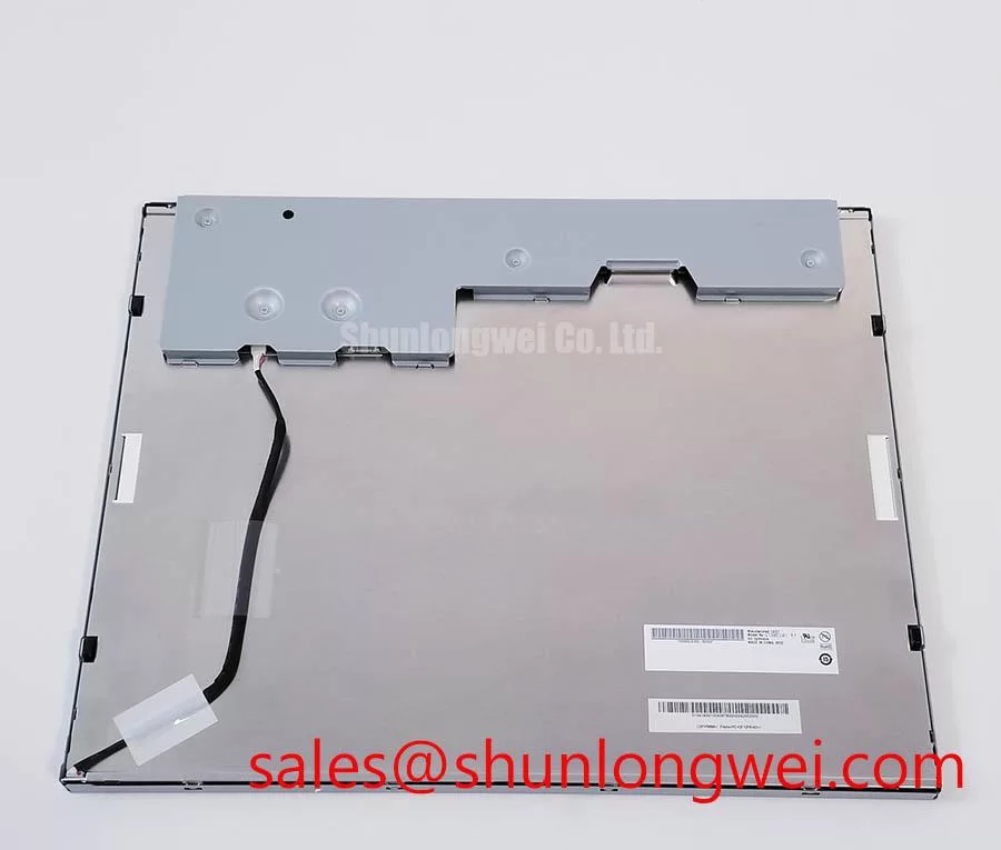
When a display assembly is received from storage or removed from an industrial console, begin with a controlled visual examination of the front optical surface, perimeter seal region, rear metal housing, and cable exits. Moisture exposure can affect an assembled display system in several ways, including contamination at connectors, corrosion risk at external interfaces, and optical changes that become visible only after the unit returns to operating temperature.
The 60°C / 90% RH condition is not an official operating or storage rating stated here for the G190EG01 V0. It should be treated as a Design Consideration when evaluating equipment cabinets exposed to humidity, condensation cycles, or enclosure leakage. System engineers should verify the panel’s original environmental limits and compare them with measured cabinet conditions before approving continued use.
Cold start behavior also deserves attention where an HMI console is exposed to low ambient temperatures. Liquid-crystal response can appear slower when temperature falls, which may be observed as delayed grayscale transitions, temporary image persistence, or reduced motion clarity. These symptoms should not automatically be attributed to panel failure. Verify the panel temperature, host timing stability, backlight state, and signal source against a known-good path before determining whether replacement is required.
Backlight dimming must be assessed at the system level. The requested PWM range of 200 Hz to 1 kHz is an Engineering Recommendation context rather than an official parameter for this AUO model. The backlight driver, brightness control signal, cable length, and enclosure acoustics determine whether visible modulation or audible effects occur. Designers should measure brightness response across the actual control range and verify that the selected dimming method remains stable during low-temperature startup and changing supply conditions.
For equipment used near exposed navigation stations or other high-humidity industrial locations, enclosure sealing, drainage paths, connector protection, and service access should be evaluated as one assembly. The display module itself should not be treated as the sole environmental barrier. Useful broader integration guidance is available through Industrial Display & HMI Solutions, particularly when panel selection must be coordinated with enclosure, thermal, and interface controls.
Managing Localized Thermal Gradients and Optical Color Shift
Check the rear housing and surrounding mechanical structure for evidence of uneven heat exposure before replacing a panel that shows brightness variation or color shift. A display may receive thermal loading from nearby processors, power supplies, inverter boards, sunlight through a console window, or inadequate airflow around narrow mounting edges. The observed image condition may relate to the panel, its backlight driver, the host power system, or the surrounding mechanical design.
Localized thermal gradients should be managed as a Design Consideration. Where a system uses metal support rails or chassis contact points around the display opening, engineers should evaluate whether these structures distribute heat evenly without imposing panel stress. The original mounting arrangement should be retained where practical, because altered clamp locations, excessive frame pressure, or a distorted cutout can create optical nonuniformity and mechanical loading.
Optical yellowing, reduced brightness, and color imbalance are system-level aging observations rather than official lifetime predictions for G190EG01 V0. No specific L70 or B50 operating-life figure is stated as an official specification here. The maintenance approach should instead compare backlight current behavior, brightness consistency, power stability, and thermal conditions with a known-good assembly or the original equipment service documentation.
Signal routing also matters in electrically noisy industrial cabinets. A 100 Ω differential impedance target with controlled pair skew is a general LVDS Design Consideration, not a confirmed interface specification for this exact model. The system integrator should first verify whether the original panel interface uses LVDS, TTL, or another signaling arrangement. If differential signaling is confirmed, the display cable and host PCB should preserve pair symmetry and maintain clean return-current paths to reduce susceptibility to switching noise and pixel-clock instability.
For projects that require comparison with another display assembly, M185XW01 VE can be reviewed as a separate verified display option. It should not be assumed to be a direct replacement solely because of application similarity. Mechanical dimensions, connector orientation, resolution, interface format, brightness characteristics, mounting positions, and controller timing must be confirmed individually.
⚡ Practical Risk Reminder: Disconnect system power and allow stored energy in the display power path to discharge before inserting or removing any panel or backlight connector.
Wide Viewing-Angle Considerations for Multi-Angle Consoles
Evaluate the image from the normal operator position and from the practical off-axis positions expected around the equipment console. A panel that appears acceptable head-on can show contrast, grayscale, or color changes when viewed from above, below, or from either side. This examination is especially relevant where more than one operator may read status graphics, alarm messages, process trends, or navigation data from different positions.
The 85/85/85/85 viewing-angle figure and the stated Super-IPS or MVA technologies are not official factory specifications supplied here for G190EG01 V0. They must not be attributed to this model without the matching AUO datasheet. In replacement work, engineers should confirm the original panel’s viewing-angle requirement and judge the installed module under the actual controller image, rather than relying on generic panel-family assumptions.
Anti-glare surface behavior should also be assessed directly. Under high ambient illumination, reflections can reduce perceived contrast even when the LCD produces a stable image. The front cover lens, air gap, gasket geometry, and external light direction all influence visibility. For potential use in marine radar or navigation bridge consoles, the display should be evaluated as part of the complete sealed console assembly, including screen cover, backlight control, and operator viewing distance. This is a compatibility example, not a claim that the G190EG01 V0 carries a marine-specific certification or environmental approval.
LED backlight maintenance planning should avoid unsupported operating-life numbers. The requested 50,000-hour brightness-decay reference is not verified as an official rating for this panel. A more defensible service procedure is to document present brightness, compare white-field uniformity, inspect driver behavior, and determine whether the observed reduction follows the display module, the backlight supply, or the front optical stack.
Where a host system includes another display channel or related panel electronics, the system documentation for NL192108AC21-01 may provide a useful reference point for reviewing power architecture and display-interface integration. It remains a separate product and requires independent electrical and mechanical compatibility verification.
Differential-Interface Routing Considerations for High-Frequency Jitter Control
Confirm connector keying, pin count, cable orientation, and host-board signal assignment before applying power to the G190EG01 V0. A display can remain blank, show incorrect colors, display split imagery, or exhibit intermittent artifacts when the host controller’s data mapping, interface voltage, timing, or power-up sequence does not match the original panel requirement.
The required logic supply voltage must be verified from the original panel documentation. It must not be assumed that this model accepts either 3.3 V or 5.0 V. Likewise, the power-on rise-time condition of 0.5 ms < t1 < 10 ms is not presented as an official requirement for this AUO module. It is a system timing topic that should be checked against the authoritative panel specification and the host controller waveform.
JEIDA and VESA mapping compatibility is particularly important when the electrical interface and connector appear physically compatible. Different mapping conventions can produce unexpected color ordering, corrupted pixels, or partial image behavior even when the clock is present. Engineers should compare the original controller output format, panel data format, bit depth, timing polarity, and enable sequencing before changing the panel or cable assembly.
A controlled differential route is an Engineering Recommendation when LVDS is verified for the original design. Maintaining pair symmetry, limiting discontinuities at flex transitions, and avoiding unnecessary routing near high-current switching nodes helps preserve eye quality. The stated 100 Ω differential characteristic impedance and 50 ps skew budget are general design references, not official G190EG01 V0 requirements. The final routing acceptance should be based on oscilloscope measurements, transmitter capability, cable construction, and image stability across the intended operating conditions.
When image artifacts occur after installation, inspect the connector seating first, then verify logic rail behavior, enable sequencing, panel timing, and the known-good signal path. Clock jitter and insufficient data hold time may contribute to unstable image presentation, but no single symptom identifies one cause without measurement. A disciplined comparison between the removed assembly and the replacement installation provides a more reliable basis for repair decisions.