
Content last revised on October 28, 2026
Transient Dynamics & Electrical Design: Optocoupler vs Digital Coreless Transformer on GD35PJX120L3S_B20
Compare the isolation channel’s input command with its secondary-side gate output while adjacent switching nodes change state. As a Design Consideration, interference that appears only during power switching warrants examination of the isolation channel, its auxiliary supply, and the gate-return path before condemning the module. Use appropriately rated differential measurement equipment and short probe connections so that pickup in the measurement loop does not masquerade as a gate disturbance.
Optocoupler and digital coreless-transformer drivers require different device-level checks, but neither technology establishes compatibility by name alone. Review propagation delay, channel-to-channel timing, common-mode transient immunity, output drive capability, and behavior during supply undervoltage. The relevant question is whether the complete driver maintains the intended gate state throughout the switching event, including startup and shutdown, rather than whether one isolation technology is generally newer.
Reinforced isolation is a property of a documented insulation arrangement, not an assumption that follows from a high test-voltage figure. As a Design Consideration, distinguish the driver’s isolation test rating from its working-voltage classification and from the module’s collector-emitter rating. Determine creepage and clearance from the applicable equipment requirements, insulation category, pollution conditions, and actual board geometry. A barrier can be compromised by contamination or a conductive mounting feature even when the isolated driver itself has suitable documentation.
Inspect the board surface around isolation slots and terminal barriers after cleaning. Residue, conductive dust, damaged coatings, and moisture tracks deserve attention before a power test. In cabinets exposed to temperature changes, coordinate restart with the equipment’s condensation-control procedure. Increasing separation on a drawing does not address a wet or contaminated surface in the installed assembly.
The driver’s auxiliary supply also belongs in this investigation. The general operating principles of an active-clamp flyback converter help explain one auxiliary-power topology, but do not identify the topology used in this module or its host equipment. During diagnosis, observe the actual isolated supply at the driver while switching occurs; supply disturbances and reference movement can resemble a failure of signal isolation.
Housing appearance is not a reliable basis for assigning insulation or temperature properties. Background information on polyphenylene sulfide engineering plastic describes that material generally; it does not establish the housing material of the GD35PJX120L3S_B20. For maintenance decisions, concentrate on documented assembly limits and visible damage around mounting points, terminals, and barriers rather than inferring material performance from color or surface texture.
Field Diagnostics & Commissioning: Retrofit Assessment and Turn-On/Turn-Off Tuning in GD35PJX120L3S_B20 Topologies
Record the existing turn-on and turn-off gate-resistor arrangements before changing the power module or driver board. As an Engineering Recommendation, preserve the original circuit configuration as the diagnostic baseline, then evaluate switching behavior under controlled operating conditions. A resistance value that worked with the previous assembly does not automatically reproduce its switching losses, overshoot, or gate stability after a hardware change.
Where the driver provides separate turn-on and turn-off paths, assess them independently. Faster turn-on can alter current commutation and ringing; faster turn-off can increase voltage overshoot associated with the power loop. Slowing either transition can increase switching energy. The appropriate adjustment depends on measured waveforms, driver capability, thermal performance, and protection response, with final settings established by the responsible system engineer.
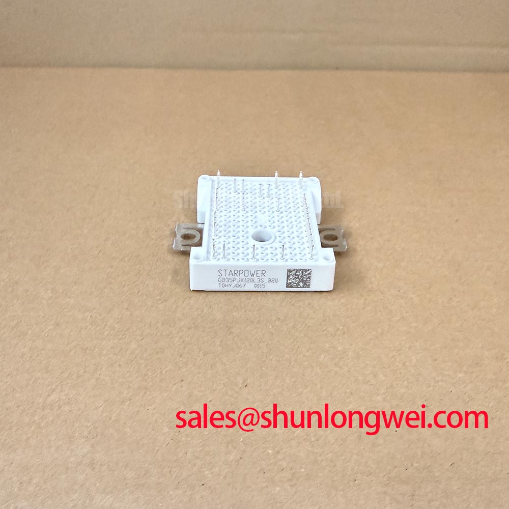
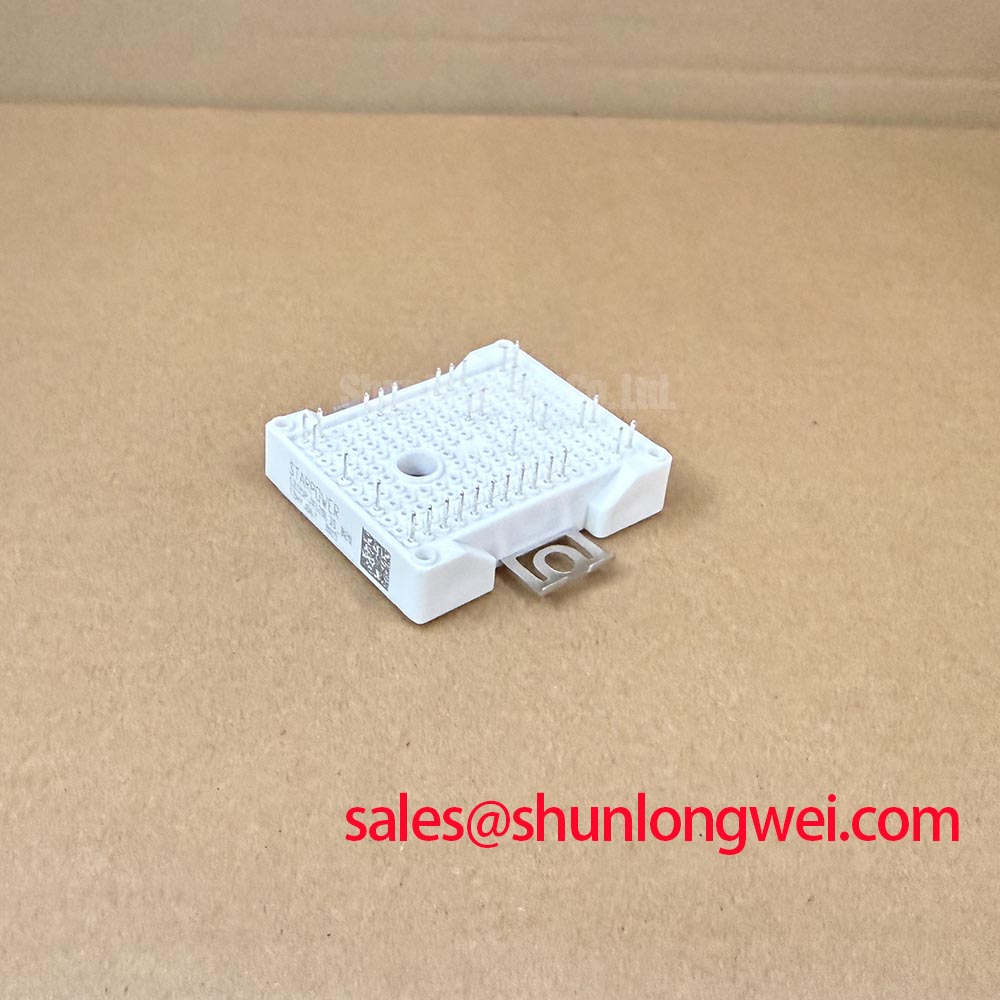
The CM35MX-24A can be included in a replacement assessment, but it should not be described as a verified direct replacement without an electrical and mechanical compatibility record. The comparison below separates confirmed GD35PJX120L3S_B20 data from the checks that establish interchangeability.
| Selection item | GD35PJX120L3S_B20 | CM35MX-24A comparison requirement |
|---|---|---|
| Manufacturer | StarPower | Consult manufacturer datasheet |
| Specified voltage rating | 1200 V — Official Specification | Verify rating and applicable conditions |
| Specified current rating | 35 A — Official Specification | Verify rating and temperature conditions |
| Package designation | Power Module — Official Specification | Compare outline, mounting, and terminals |
| Internal circuit and terminal assignment | Consult datasheet | Match against the installed schematic |
| Gate-drive and thermal compatibility | Assembly-specific assessment required | Evaluate before substitution approval |
For possible use in high-dynamics multi-axis CNC or robotics servo equipment, the compatibility review should include repeated acceleration, deceleration, and simultaneous axis loading. These are equipment-level evaluation conditions, not a claim that this module is qualified for a particular machine. Check how the existing controller handles regeneration and whether the DC-link protection remains coordinated with the installed power stage.
Trace the complete power path before ordering associated components. A comparison involving FP35R12KT4 should begin with its circuit configuration and the equipment schematic; its role cannot be assigned as an upstream rectifier or complementary stage solely from its part number. Where the existing system contains phase-controlled rectification, investigate firing control and line-side disturbances separately from inverter switching. Gate-resistor adjustment at the inverter is not a remedy for rectifier-generated supply harmonics.
Parallel operation requires its own design review. A positive temperature coefficient of on-state voltage can assist static sharing only within the operating region where that behavior is documented. Do not assume that characteristic for this exact module from its current rating. As a Design Consideration, matched thermal conditions, balanced gate paths, and symmetrical power connections help reduce imbalance, while transient current sharing still requires measurement.
During reassembly, inspect heatsink flatness and contact surfaces, remove debris without damaging the interface, and apply the approved thermal-interface process. Assess compound condition when the module is removed rather than assigning an unsupported universal replacement interval. Terminal tightening should follow the documented hardware procedure; repeated tightening without inspection can damage connections instead of improving them. Record the work so subsequent temperature comparisons have a meaningful baseline.
Field Diagnostics & Commissioning: Suppression of Motor-Cable Voltage Reflections in GD35PJX120L3S_B20 Topologies
Measure switching voltage at the motor terminals as well as at the drive output when long motor cables are involved. As a Design Consideration, a cable behaves as a transmission line when the switching edge is fast relative to its propagation time. Reflections at an impedance mismatch can produce a terminal excursion approaching twice the incident voltage step under idealized conditions; this is not a guaranteed peak for every installation or a GD35PJX120L3S_B20 specification.
Separate that motor-terminal phenomenon from collector-emitter overshoot at the module. Motor-terminal stress depends on cable propagation, termination, and the applied waveform, while local semiconductor stress also depends on commutation-loop inductance and switching current. Use consistent probe references and suitable measurement bandwidth when comparing locations. A waveform captured at one end of the cable cannot establish the peak at the other end.
Output-filter and choke selection should follow the measured problem. As an Engineering Recommendation, assess cable characteristics, motor insulation requirements, switching frequency, output current, and filter heating together before selecting a dv/dt filter or reactor. The resulting assembly should be checked across its intended operating range, including low-load and regenerative conditions. Adding inductance without reviewing resonance and voltage drop can exchange one integration problem for another.
For local switching overshoot, examine the physical commutation path and the placement of any existing suppression components. The discussion in Mastering Power System Dynamics provides background on stray inductance and snubber behavior. Apply those principles to the actual assembly: minimize unnecessary loop area, preserve intended return paths, and validate suppression through switching measurements rather than copying component values from an unrelated drive.
Regenerative braking presents a different voltage-control task. During deceleration, returned mechanical energy can raise the DC-link voltage even when cable reflections are well controlled. Review the installed braking chopper, resistor connections, thermal protection, and controller response against the equipment design. An output filter does not replace DC-link energy management, and a braking resistor should not be sized from the module’s current rating alone.
Maintenance Note: Trend terminal temperature rise under comparable loading and check heatsink airflow before increasing duty on a repaired assembly. Keep cooling passages clear, confirm fan operation, and investigate localized heating at connections without treating it as proof of a single fault. Schedule cleaning and interface inspections according to contamination, thermal trends, and the equipment manufacturer’s maintenance procedure.
Close the commissioning record with the cable arrangement, gate-drive configuration, suppression hardware, cooling condition, and captured voltage waveforms. For installations with altitude or radiation-reliability requirements, obtain application-specific manufacturer guidance rather than deriving insulation margins or semiconductor failure rates from the 1200 V rating. Release the assembly only after its switching peaks, regenerative response, and thermal behavior satisfy the equipment’s documented acceptance criteria.