

Content last revised on October 18, 2026
Preventing Frame Lag and Image Smearing in Cryogenic Storage and Outdoor Industrial Facilities
When a display begins responding slowly in a cold enclosure, compare motion rendering at the actual panel temperature with the same image sequence at room temperature before changing the host controller. Liquid-crystal viscosity can increase as temperature falls, extending gray-to-gray transitions and making moving diagnostic traces appear blurred. This behavior should be separated from signal timing faults, frame-buffer delays, and an unsuitable display refresh configuration.
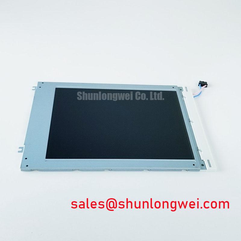
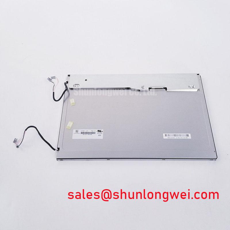
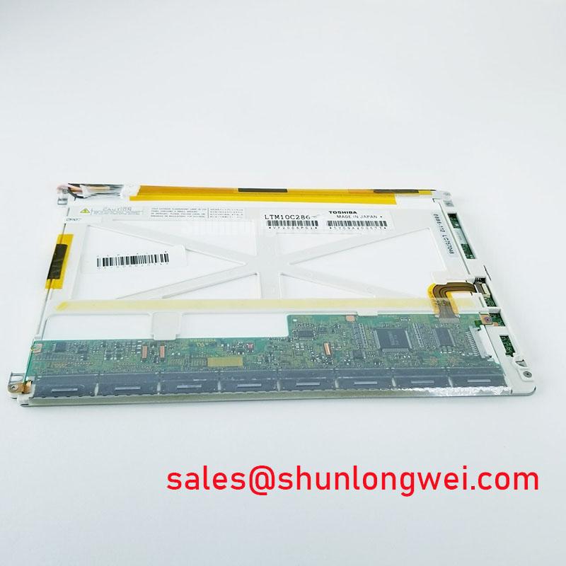
The HDM3224-1-9J1F is identified as an AUO TFT-LCD Active Matrix Color Display Module with a standard form factor. The supplied product data does not establish a specific interface, response-time rating, touch construction, optical coating, or operating-temperature certification for this model. The system integrator should verify those items against the original panel documentation and the host display controller before approving a replacement.
For an enclosure exposed to sub-zero storage or outdoor cycling, the mechanical review should include the perimeter seal, bezel compression, and any adhesive joint around the panel edge. A Design Consideration is to inspect whether the frame allows uniform thermal expansion without point loading. Localized pressure can create temporary optical non-uniformity, while uneven compression may compromise the enclosure seal during repeated heating and cooling.
High-EMI factory equipment also requires disciplined display-link routing. If the host design uses differential signaling, the PCB designer may establish a controlled differential impedance target such as 100 Ω ± 10% and manage pair skew within the system’s timing budget. These are host-interface Design Considerations, not confirmed electrical specifications of the AUO module. Route the pair continuously, avoid unnecessary stubs, and validate the received eye opening and clock stability at the panel connector under servo and inverter switching conditions.
For broader enclosure, display, and HMI integration principles, engineers can refer to Industrial Display & HMI Solutions. That reference is useful when assessing thermal airflow, sealing strategy, cable routing, and service access as one mechanical and electrical assembly.
Single Vertical Hairline Defect and Sub-Pixel Column Driver Open-Circuit Localization
A single vertical line should first be classified by its behavior across solid red, green, blue, black, and white screens. A line that remains fixed through each primary-color image deserves a different inspection path from a transient image artifact that changes with the source signal or panel timing.
Use a controlled three-screen bench sequence with red, green, and blue full-field images, then repeat the test with black and white fields. Record whether the line is continuous from top to bottom, changes width, or disappears at a particular gray level. This approach helps separate a possible column-driver interruption from an image-data problem upstream. It does not, by itself, establish the failed internal element.
A 45-degree flashlight inspection can help reveal whether the apparent defect is within the displayed image or related to the surface and backlight. With the panel displaying a dark field, sweep the light across the surface without pressing the bezel. A reflection that changes with viewing angle may indicate surface contamination, a cover-layer mark, or optical non-uniformity. A line that remains locked to the active image area requires investigation of the panel drive path and connector seating.
COG and edge-driver regions are mechanically sensitive. During service, support the module evenly and avoid pressing the active area while reconnecting the display cable. The correct inspection sequence includes checking connector alignment, cable insertion depth, latch engagement, and strain relief before attributing the symptom to an internal driver fault. A known-good source pattern and oscilloscope comparison at the host side can help identify whether the line is being created before the panel.
For surgical navigation or ultrasound diagnostic display assemblies, visual defect acceptance should be defined by the equipment manufacturer’s service specification rather than by a general LCD rule. Direct sunlight, viewing angle, contrast, and anti-glare performance can change the apparent severity of a thin line. The supplied data does not confirm a specific contrast ratio, sunlight readability rating, or anti-glare coating for this model.
Surface Anti-Glare and Anti-Reflective Treatment for High Ambient Readability
Evaluate the screen under the actual lighting geometry of the equipment rather than judging readability under diffuse workshop lighting. Reflections from surgical lamps, overhead luminaires, windows, and polished instrument surfaces can mask low-contrast details even when the panel image itself is stable.
Anti-glare and anti-reflective treatments perform different optical functions. An AG surface scatters reflected light to reduce sharp mirror images, while an AR treatment is intended to reduce surface reflection through optical-layer design. The trade-off may include changes in apparent black level, sparkle, haze, or fine-detail clarity. These characteristics must be measured on the complete display assembly, including any cover lens, bonding layer, bezel, and protective film.
Do not treat a general viewing-cone value as a confirmed characteristic of the HDM3224-1-9J1F. The supplied product information confirms the product category and construction, but it does not provide a verified TN, IPS, or MVA classification, nor a confirmed symmetric viewing-angle specification. Engineers should compare grayscale steps and color stability from the real operator position before approving the panel for an HMI or medical visualization subsystem.
Backlight evaluation should follow the installed driver architecture. Check for brightness drift, uneven illumination, startup behavior, and thermal changes at the rear of the module. A constant-current driver may improve LED current consistency, but its operating limits, fault response, and dimming method remain system-level matters unless explicitly documented for the panel. The supplied information does not establish an LED half-life, MTBF value, or brightness-retention curve for this model.
Maintenance Note: Inspect the enclosure airflow path and perimeter gasket condition during scheduled service so dust buildup or uneven compression does not alter optical performance or increase local panel stress.
Optical terminology can be reviewed through AUO’s Industrial Display & Embedded Systems information and the technical discussion of optical diffusers and brightness-enhancement films. These references provide industry context, not model-specific confirmation.
Backlight Driving, PWM Dimming, and Flicker Suppression
When replacing a display in a diagnostic terminal or industrial HMI, identify the installed backlight architecture before connecting power. A host designed for a particular LED enable, dimming, and current-control arrangement should not be assumed compatible with a different backlight topology. The system integrator should verify the required supply voltage, connector pinout, enable logic, dimming method, and protection behavior from the original panel documentation.
CCFL ignition characteristics and LED constant-current operation are fundamentally different. A legacy cold-cathode system may require a dedicated inverter and high-voltage starting process, whereas a solid-state LED assembly normally depends on a current-regulated driver and an appropriate enable or dimming interface. No CCFL, WLED, PWM ratio, or driver threshold is confirmed in the supplied specification for the HDM3224-1-9J1F, so these characteristics should not be assigned to the module without documentation.
For flicker assessment, observe the complete optical output with a photodetector or a suitable high-speed camera while varying the host brightness command. A nominally stable image can still produce visible modulation if the driver frequency, duty-cycle range, camera exposure, and room lighting interact unfavorably. If a PWM control path is used by the host system, its frequency and dimming range should be selected through system testing rather than copied from an unrelated panel.
Cold operation also affects the liquid-crystal response and the perceived relationship between backlight brightness and motion clarity. A heater strip, if present in the equipment, is an enclosure-level accessory and must not be treated as part of this AUO module. Validate heater control, condensation prevention, display timing, and backlight startup as separate functions. During final testing, monitor the panel connector, controller output, and image response while the equipment transitions through its specified environmental profile.