Shunlongwei Co. ltd.
IGBT Module / LCD Display Distributor
Customer Service
+86-755-8273 2562
IGBT Module / LCD Display Distributor
“The ADC interface of the single-chip microcomputer belongs to the analog-to-digital conversion interface, which converts the external analog signal into a digital signal. At present, many single-chip microcomputers in the market have their own ADC conversion interface. If there is no ADC conversion interface, the ADC digital-to-analog conversion chip can be used for external expansion.
“
The ADC interface of the single-chip microcomputer belongs to the analog-to-digital conversion interface, which converts the external analog signal into a digital signal. At present, many single-chip microcomputers in the market have their own ADC conversion interface. If there is no ADC conversion interface, the ADC digital-to-analog conversion chip can be used for external expansion.
The ADC module converts the analog signal into a digital signal. The digital signal is represented by 0 and 1. The ADC module has a reference voltage. Suppose the given reference voltage is 5V, and the ADC is 12-bit (a few digits indicate that the analog quantity is stored in binary digits.) The converted digital quantity, the 12-bit ADC can store the digital quantity range: (binary) 000000000000~111111111111, and the converted decimal number range is 0~2^12 or 0~4095.
That is to say, the reference voltage is divided into 2^12 parts, that is, 4096 parts, and the minimum resolution is VREF/4096.
That is to say, binary 000000000000 represents the input analog quantity 0V, and 111111111111 represents the maximum value VREF.
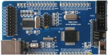
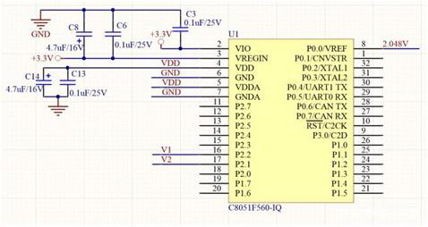
The C8051 single-chip microcomputer in the above figure is an example. As shown in the schematic diagram, the working power supply of the single-chip microcomputer is 3.3V, and the reference voltage is 2.048V, so the input range of the analog quantity is 0~2.048V. If the voltage range to be collected is greater than the reference voltage value, you can use a resistor divider to step down or use an op amp to reduce it.
The microcontroller ADC is 12-bit. That is to say, when the input voltage is 0, the digital result converted by the microcontroller is 000000000000 (binary), and when the input voltage is 2.048V, the digital result converted by the microcontroller is 111111111111 (binary), and the decimal is 4095.
That is to say, the value of the input voltage V=2.048×the digital quantity collected by the ADC÷4095.
For example, if we want to collect an analog voltage in the range of 0~10V for Display, then we can first reduce the voltage of 0~10V by 5 times, you can use resistor divider, you can also use op amp reduction, etc., and then connect to the microcontroller The ADC sampling port can be connected to the P2.2 port in the figure above.
The final conversion formula is: V = result * 2.048/ 4095 * 5; where result is the digital quantity collected by the microcontroller.
The Links: SEMIX353GB126V1 G104SN03-V3