Content last revised on October 1, 2026
Preventing Spurious Faults: High-Frequency Commutation Loop Inductance Guidelines for J2-Q02A-F
| Hardware Specification | J2-Q02A-F |
|---|---|
| Manufacturer | Mitsubishi Electric |
| Component type | Power Hybrid IC / IGBT Module |
| Application class | 400 W servo amplifiers, 0.4 kW |
| Rated voltage class | 200 V to 230 V AC |
| Module technology | Insulated Gate Bipolar Transistor |
| Package | SIP with metal backplate |
| Mounting | Through-hole solder connection and heatsink screw mounting |
| Operating temperature | −20 °C to +85 °C case temperature |
| Country of origin | Japan |
With the DC link discharged, measure resistance and diode behavior between the accessible power terminals against a known-good assembly, then inspect the solder joints, bus connections, and heatsink interface before applying a switching test. A reading that differs materially from the reference path can indicate a damaged power junction, an incorrect terminal connection, or a parallel circuit affecting the measurement; isolate the module from surrounding components before assigning a fault.
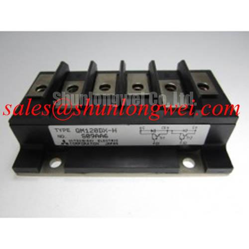
The J2-Q02A-F is identified in the supplied hardware data as a power hybrid IC using IGBT technology for 400 W servo amplifier applications in the 200 V to 230 V AC class. Its SIP construction and metal backplate place the commutation path, terminal orientation, solder quality, and heatsink installation directly in the troubleshooting sequence. A replacement should therefore be checked against the original terminal layout and mechanical interface rather than selected by voltage class alone.
During an oscilloscope test, probe the switching node with a suitable differential probe and use the shortest practical connection to the reference point. Excessive probe-loop area can create ringing that is not present at the semiconductor terminals. Compare turn-on and turn-off waveforms at the same operating condition, recording the DC-link voltage, gate command, collector-emitter behavior, and any desaturation or overcurrent response generated by the servo amplifier.
Design Consideration: Minimize the high-frequency commutation loop area to reduce parasitic inductance and switching overshoot. The resulting peak voltage is influenced by the DC-link voltage, stray inductance, and current slew rate, so the system designer must verify the measured peak against the module voltage boundary during switching tests. A snubber or clamp network may be evaluated when the measured ringing exceeds the system tolerance, but its capacitance, damping, pulse current, and dissipation must be selected from the actual switching waveform.
Plan the power and return conductors with a compact, symmetrical geometry where the mechanical construction permits it. Keep gate-drive and power-current paths separated from sensitive feedback wiring, and avoid routing encoder, current-sensor, or fault-input conductors alongside the high di/dt loop. The relevant design target is low parasitic coupling, not a universal clearance or inductance number that can be applied to every servo amplifier.
When a low-voltage traction controller for an electric forklift or warehouse vehicle is being evaluated, the same checks apply at the controller level: inspect the battery-to-DC-link path, braking branch, current sensor wiring, and motor cable termination. A fault that appears only during acceleration or regenerative braking may originate in the surrounding commutation network, so compare the module waveform with the gate-driver and bus measurements before replacing the power hybrid IC. The 6DI20A-050 can be reviewed as a separate power-module reference during a cross-model mechanical and electrical comparison, subject to the original equipment documentation.
J2-Q02A-F Circuit Protection and Reliability: Thermal Cycling of the Braking Path
Check the braking transistor path, resistor connections, and DC-link voltage capture during a controlled deceleration event, then compare the recorded energy profile with the installed braking circuit ratings. Do not infer braking capacity from the 400 W application class alone because motor inertia, deceleration time, battery condition, and controller limits determine the actual pulse energy.
In a servo amplifier or low-voltage traction controller, regenerative energy can raise the DC-link voltage when the motor decelerates. The braking circuit must provide a controlled path for that energy through the appropriate switching device and ballast resistor. Whether the braking function is internal to the assembly or implemented by an external branch should be confirmed from the original schematic and terminal arrangement. The J2-Q02A-F data supplied here does not establish a separate braking resistor rating, pulse-energy limit, or internal braking topology.
For field diagnosis, inspect the resistor for discoloration, cracked ceramic material, loose terminals, and changes in resistance after the unit has cooled. Capture the DC-link waveform during repeated acceleration and deceleration commands while monitoring the braking command and fault output. A rising bus voltage with no corresponding braking command may point toward control timing, sensing, or wiring issues; a commanded braking event without effective bus control requires examination of the switching device, resistor, driver supply, and thermal path as a complete circuit.
Design Consideration: Thermal cycling is governed by the temperature difference across the semiconductor and heatsink, the duration of each pulse, the cooling system, and the mounting interface. Apply thermal interface material as a uniform, thin layer appropriate to the selected compound and surface finish. The supplied product data does not define a mandatory TIM thickness or screw torque, so the equipment assembly specification and fastener manufacturer data control those values.
Seat the metal backplate evenly against the heatsink and verify that the mounting surface is clean, flat, and free from burrs. Tighten fasteners using a controlled sequence that avoids tilting the module, then inspect soldered terminals for mechanical stress caused by heatsink movement. Field Alert: Disconnect the DC link and verify the absence of stored voltage before removing the module or inserting any connector.
The rectifier and braking branches should be assessed together because the rectifier determines how the DC link is replenished while the braking branch manages energy returned from the motor. The 1DI200K-055 may be considered as a related rectifier-stage reference, but compatibility depends on voltage, current, package, wiring, control topology, and the original equipment design.
Preventing Spurious Faults: DC-Bus Operating Voltage Headroom for J2-Q02A-F
Measure the DC bus at the module terminals during startup, acceleration, steady operation, and regenerative braking, using an instrument rated for the measurement category and switching environment. Compare the highest measured transient with the permitted system operating boundary and inspect whether the event is synchronized with motor current changes, braking commands, or upstream rectifier commutation.
The supplied specification identifies the application as a 200 V to 230 V AC class servo system and gives a case-temperature range of −20 °C to +85 °C. It does not provide a DC-bus maximum, repetitive peak voltage, short-circuit withstand time, altitude derating curve, neutron-induced failure rate, or Single Event Burnout data. Those values must not be inferred from the AC class or from the physical SIP package.
Design Consideration: At elevated installation sites, reduced cooling performance, insulation coordination, switching transients, and environmental radiation conditions may all affect system margins. A precise SEB probability or FIT value requires a documented device technology model, test method, voltage condition, neutron spectrum, altitude profile, and statistical confidence level. Without that source data, the practical engineering task is to measure the real DC-bus waveform, maintain suitable electrical clearances for the complete assembly, and validate the voltage margin under the intended operating environment.
For a forklift or warehouse traction controller, check battery voltage variation, regenerative return current, contactor operation, precharge behavior, and the voltage measured at the power module rather than only at the battery terminals. Cable resistance and inductance can make the two measurements differ during rapid load changes. A controller that faults only after a long descent or repeated stop cycle also warrants thermal inspection of the heatsink, braking resistor, and enclosure airflow.
Do not treat an external compliance label or system EMC result as a property of the module itself. Switching emissions and immunity depend on the complete inverter, enclosure, cable routing, grounding, filter network, and control firmware. The Mitsubishi Electric NX-Series IGBT Modules provides useful manufacturer-level context for power-module technology, but its ratings and construction must not be transferred to J2-Q02A-F.
Field Diagnostics and Commissioning: Isolated Driver Supply Checks for J2-Q02A-F Topologies
With the controller isolated from the motor, verify the driver supply, gate command waveform, signal reference, and fault feedback at the module interface before enabling power switching. Use the original pin documentation for the interface; the supplied data does not define individual gate, emitter, sensor, or auxiliary-supply pin assignments.
Check the driver supply for startup stability, load-dependent droop, excessive ripple, and abnormal recovery after a protection event. A missing gate command, distorted pulse, or repeated restart can originate in the isolated DC-DC converter, gate-driver protection circuit, controller interlock, or module itself. Compare the command-side waveform with the isolated-side waveform at the same time so that propagation and common-mode behavior can be separated from a power-device fault.
Design Consideration: Galvanic isolation, insulation coordination, and common-mode transient immunity must be specified for the complete driver architecture and operating voltage. The supplied J2-Q02A-F parameters do not certify a reinforced-isolation voltage or a particular CMTI rating. Designers should verify the isolation barrier, creepage and clearance, pulse transformer or isolated-driver behavior, and transient performance against the applicable equipment standard.
During commissioning, increase operating stress in controlled steps while observing the gate-to-emitter waveform, switching-node overshoot, DC-link behavior, and protection response. Keep the driver return path defined and prevent high-current switching currents from sharing the measurement reference. If a fault appears only when the motor cable is connected, compare the system with the motor disconnected and then inspect cable shielding, termination, motor insulation, and reflected switching transients.
When evaluating long-duration operation, record case temperature and the surrounding heatsink temperature rather than assuming that the stated case range represents the complete enclosure limit. The 1200 V CoolSiC™ MOSFET Advantage in Three-Phase Power Conversion article can serve as broader technology context for three-phase power conversion, while the Mitsubishi Electric SiC Power Modules and SBDs page provides separate manufacturer information that should not be used as a substitute for J2-Q02A-F documentation.
After the electrical checks, confirm the SIP body orientation, solder wetting, terminal alignment, heatsink contact, and cable strain relief. The final compatibility decision should be based on the original servo amplifier schematic, connector and pin assignment, mechanical envelope, control timing, thermal design, and measured switching behavior.