Content last revised on September 10, 2026
Dynamic Contrast Ratio Stabilization and Liquid Crystal Temperature Tracking
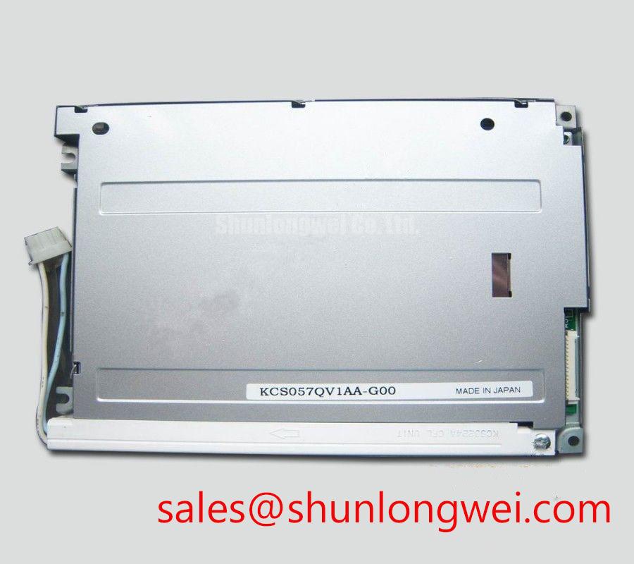
With the equipment isolated, begin the replacement check by comparing the original panel’s label, active viewing area, connector arrangement, and backlight wiring before applying power. The KCS057QV1AA-G01 is a Kyocera 5.7 inch CSTN LCD display with a 320 × 240 QVGA resolution, a 4:3 aspect ratio, an 8 bit parallel data interface, and a single CCFL backlight. These details define the practical integration boundary for legacy control equipment and should be confirmed against the host system documentation.
The KCS057QV1AA-G01 uses color STN passive matrix technology rather than an IPS or MVA TFT architecture. That distinction matters during field replacement because the panel’s grayscale response, viewing direction, and contrast behavior must be assessed as characteristics of the original CSTN system. A replacement that matches the diagonal size but uses a different optical architecture can produce altered color balance, viewing angle behavior, or controller timing requirements.
Its official active screen dimensions are 115.2 mm horizontally by 86.4 mm vertically, corresponding to a nominal 5.7 inch diagonal. Measure the visible active area rather than relying only on the outer bezel dimensions. In older forklift dashboards, operator terminals, railway cab displays, and industrial controller panels, the mechanical opening may include a separate gasket, bezel, or protective window. Those external parts can make an apparently similar display unsuitable if the active image area does not align with the original viewing aperture.
CSTN contrast can change with liquid crystal temperature and viewing direction. When a repaired system shows pale characters, darkened areas, or grayscale inversion after cold start, allow the complete panel and enclosure to reach the normal service condition before making a final optical judgment. Check the display at the actual operator viewing angle and compare it with a known good image from the host controller. This method separates a panel optical issue from incorrect display data, unstable power, or an unsuitable front window.
Anti glare treatment, ambient illumination, and the condition of the protective lens also affect perceived contrast. The supplied specification identifies the display technology and active dimensions, but it does not establish a guaranteed optical contrast ratio under direct sunlight, a viewing cone equivalent to 85 degrees in four directions, or a specific surface etching process. Those values should not be assumed from the model number. Designers evaluating the unit for a railway passenger information system or cab signalling display should verify the complete optical stack, including enclosure shading and external glazing, in the intended installation.
Backlight modulation also requires system level verification. The official information identifies a single cold cathode fluorescent lamp, but it does not specify a PWM frequency, duty cycle linearity, or an approved dimming method for this particular panel. If the host equipment varies lamp brightness, the integrator should confirm that the dedicated inverter and its control signal are compatible with the original display assembly. Audible inverter noise, visible flicker, and uneven brightness should be checked under both minimum and maximum commanded brightness.
Parallel Bus Synchronization and Logic Power Rail Verification
The KCS057QV1AA-G01 is specified with an 8 bit parallel data bus. This is a central compatibility point. It should not be treated as a TTL 24 bit RGB panel, an LVDS panel, or a generic serial display without confirming the original controller interface. A host board designed for a different pixel bus may require a separate interface redesign, and the display cannot be described as a direct electrical replacement solely because the resolution is the same.
During troubleshooting, inspect the host controller documentation and identify the actual signal names, enable timing, clock relationship, and logic thresholds before probing the connector. A clean static image with incorrect colors can result from data bit ordering or controller configuration, while a split image or unstable frame can involve timing, connector contact, power integrity, or a damaged host output. Use the original working signal path as the reference and compare the replacement panel under identical controller settings.
The supplied factory parameter set does not state the KCS057QV1AA-G01 logic supply voltage, power on rise time, JEIDA or VESA mapping, differential impedance, or differential pair skew. Accordingly, values such as 3.3 V, 5.0 V, 100 ohms, or a specific sub nanosecond skew limit must not be assigned to this model without the original Kyocera documentation. The system integrator should verify the required supply voltage and timing conditions from the original panel documentation before connecting the display.
For a parallel interface, practical inspection should focus on connector orientation, ground continuity, shorted adjacent conductors, and the relationship between the host data lines and the panel timing signals. Keep the signal return path controlled according to the host board design, especially where the display cable runs near inverter wiring or motor drive conductors. This is a design consideration rather than a model specific guarantee: reducing unnecessary loop area and separating signal wiring from noisy power wiring can help limit interference, but final acceptance requires measurement on the completed assembly.
When a railway information terminal or cab display is being repaired, confirm that the graphics controller actually produces the format expected by this QVGA panel. The 320 × 240 resolution and 4:3 format support direct pixel mapping in suitable legacy systems, but the controller firmware, frame timing, character generator, and color handling remain system responsibilities. No external frame grabber or scaling device should be presumed necessary unless the host architecture requires one.
Radiated Emissions and Backplate Grounding in the Completed Assembly
A display module does not independently pass CISPR Class A or Class B limits. Emissions depend on the host controller, cable routing, enclosure, inverter, grounding arrangement, and the operating state of the complete equipment. This is especially important when the panel is installed near variable frequency motor drives or other high energy switching assemblies. Pixel jitter, horizontal bands, or intermittent contrast changes should be investigated with the display supply, data cable, backlight inverter, and nearby power conductors considered together rather than assigning the symptom to one part without measurement.
The CCFL backlight requires a dedicated high voltage AC inverter. The supplied application data describes an approximate 500 to 800 Vrms striking voltage requirement and identifies the need for high voltage safety isolation. The actual inverter must be selected and controlled according to the original panel assembly documentation. Verify lamp connection polarity where applicable, insulation spacing, cable condition, shielding, and the inverter’s enable behavior. Do not energize an exposed CCFL circuit during routine connector inspection.
⚠️ Field Alert: Disconnect power and allow the CCFL inverter circuit to discharge before inserting or removing the display cable.
For interference diagnosis, first reproduce the fault with a stable test image and then observe whether the disturbance changes when the backlight is enabled, when the data cable is repositioned, or when nearby switching equipment changes operating state. These observations can indicate whether the disturbance is entering through the logic interface, the display supply, the inverter wiring, or the enclosure reference. Confirm the finding with an oscilloscope or suitable emissions test arrangement against a known good signal path.
Grounding should follow the equipment’s approved protective earth and signal reference architecture. A multi point connection to a metal backplate may be appropriate in some systems, while a poorly controlled connection can create circulating currents or add noise to the panel reference. The KCS057QV1AA-G01 factory parameter set does not define a star grounding layout, a 360 degree shield termination, ferrite material, or a guaranteed immunity level. These remain design considerations to be validated on the final equipment.
For practical industrial display evaluation, engineers can use the guidance in Industrial Display and HMI Solutions when reviewing enclosure installation, wiring separation, service access, and environmental test planning. External references on Low Voltage Differential Signaling interface architecture may help explain why LVDS practices should not be transferred automatically to this model’s specified 8 bit parallel bus. The Tianma industrial display resource is also useful for general comparison of industrial display technologies, but it is not a specification for this Kyocera part.
CCFL Backlight Service and Retrofit Assessment
Backlight faults should be separated from image generation faults before replacing the panel. If the screen contains valid graphics when viewed under controlled external illumination, investigate the CCFL inverter, lamp connection, enable signal, and high voltage insulation path. If the image data itself is absent, changing the lamp assembly will not correct a controller, cable, or logic supply problem. This distinction is valuable during emergency repair because the KCS057QV1AA-G01 combines a legacy passive matrix display with a dedicated fluorescent backlight system.
The official backlight description is one CCFL. It does not specify a factory LED retrofit kit, LED conversion dimensions, constant current requirements, PWM dimming ratio, acoustic performance, optical half life, or a guaranteed operating life. A CCFL to LED conversion therefore requires a system level optical and electrical assessment rather than a simple lamp substitution. The installer should verify active area illumination, brightness uniformity, thermal behavior, mechanical clearance, insulation, and the controller’s dimming interface after any modification.
Do not infer that a modern LED driver can connect directly to the original CCFL wiring. A CCFL inverter generates the high voltage AC waveform needed by the fluorescent lamp, while an LED assembly requires a compatible current controlled supply. Reusing an unsuitable inverter can lead to unstable illumination or stress on the retrofit assembly. The retrofit designer should establish the required electrical topology from the replacement light source documentation and test it with the panel installed in its final bezel.
Uneven brightness can also originate outside the lamp. Inspect the front window, reflector area that is externally accessible, bezel pressure, cable routing, and enclosure shadows. Avoid claiming a proprietary light guide, diffuser material, or thermal construction unless Kyocera documentation confirms it. For long service intervals, designers should assess local heat accumulation around the backlight and inverter, then verify temperature distribution under the actual enclosure conditions instead of relying on a generic lifetime figure.
For railway passenger information systems and cab signalling displays, compatibility review should include the original mechanical cutout, the 4:3 image format, the host’s 8 bit parallel interface, and the CCFL inverter arrangement. The KCS057QV1AA-G01 may be evaluated for such legacy equipment only when those interfaces and environmental conditions match the source assembly documentation. Procurement teams should provide the complete existing panel label and connector information when requesting a replacement assessment from a distributor.