Content last revised on September 22, 2026
Preventing Frame Lag and Image Smearing in Cryogenic Storage and Outdoor Industrial Facilities
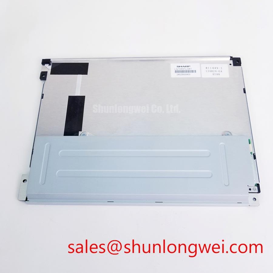
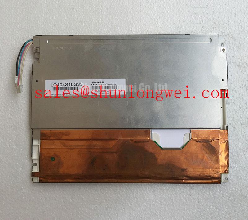
Before fitting the Sharp LQ104S1DG31, inspect the display module for frame damage, connector contamination, uneven gasket contact, and signs of pressure around the viewing area. Confirm the replacement marking against the equipment service record, then compare the original panel documentation for interface pinout, supply requirements, backlight arrangement, timing, and mounting geometry.
The LQ104S1DG31 is identified as a Sharp TFT LCD Display Module for industrial grade LCD and HMI applications. The available factory context confirms the manufacturer, product category, and module construction, but it does not provide a complete electrical datasheet in the supplied specification set. Values such as active area, resolution, luminance, contrast ratio, viewing angle, response time, backlight type, connector pin assignment, and operating temperature should therefore be taken from the original Sharp documentation or the equipment manufacturer’s service data rather than inferred from the model code.
When this panel is assessed for cold storage equipment, outdoor monitoring cabinets, or other installations exposed to thermal cycling, begin with the system’s actual temperature limits and the display documentation. Liquid crystal viscosity can increase at low temperature, which may produce slower visible transitions or image persistence. That behavior is a general LCD design consideration and is not a confirmed performance rating for the LQ104S1DG31 unless the applicable Sharp specification sheet states it.
During a cold start evaluation, allow the complete display assembly to reach the test condition before judging image quality. Observe moving grayscale patterns, fine text, and high contrast transitions rather than relying on a static screen. If the image appears delayed or smeared, compare the same signal path at normal temperature and inspect the source timing, panel supply stability, T-CON behavior, and backlight operation. This approach avoids assigning a single cause to a symptom that may involve the host controller, cable routing, display timing, or the panel itself.
High EMI factory environments require careful control of the display cable path. As a Design Consideration, differential pairs should be routed as a controlled transmission structure with continuous reference and matched path lengths. A commonly used LVDS target is 100 Ω differential impedance, but the correct value, tolerance, connector arrangement, and skew budget must be verified against the original interface specification for this panel. Do not assume that a 20 pin or 30 pin connector, JEIDA mapping, VESA mapping, or a particular signal order applies without documentation.
For a suspected frame lag problem, use an oscilloscope on the known good signal path and compare clock, data activity, enable timing, and supply behavior during the same display pattern. Inspect the cable shield termination and keep high current switching conductors away from the display interface. If the module is installed behind a sealing gasket, check that the gasket does not twist the frame or load one corner more heavily than the others. Mechanical distortion can appear as nonuniform brightness or localized optical irregularity and should not be confused with a timing fault.
For a same size or same resolution replacement evaluation, engineers may review the LMS700KF01-001 as a separate compatibility candidate. It should only be considered after comparing its mechanical envelope, interface, optical characteristics, power requirements, and controller compatibility with the installed system.
High Voltage Striking Potential and Secondary Coil Insulation Testing
The supplied factory information does not confirm whether the LQ104S1DG31 uses a CCFL backlight, an LED backlight, or a particular backlight driver arrangement. The system integrator should verify the required backlight technology from the original panel documentation before applying power. A CCFL inverter and a constant current LED driver are not interchangeable, and their start-up behavior, insulation requirements, control signals, and fault responses differ substantially.
Where the installed display system uses a high voltage CCFL inverter, service personnel should treat the secondary circuit as a high energy area. The exact striking voltage, insulation test voltage, clearance, creepage, and test duration must come from the inverter and panel documentation. The figures sometimes associated with cold cathode ignition are not official ratings for this Sharp module based on the supplied data, so they should not be used as a replacement design limit.
Insulation testing should be performed on the applicable disconnected subassembly using an approved procedure for the equipment. Protect the LCD electronics, T-CON circuitry, and control board from an inappropriate megohmmeter or hipot connection. A service test should identify the exact nodes under test, the permitted test level, and the acceptance criteria. Those limits are system determined unless the manufacturer’s documentation states otherwise.
For an LED backlight system, confirm the driver’s current regulation method, enable logic, dimming interface, and protection behavior. Do not assume a 1000:1 PWM dimming ratio or a particular brightness half-life for the LQ104S1DG31. Backlight lifetime depends on the specified LED assembly, drive current, thermal environment, optical stack, and system operating profile. No field lifetime or failure-rate claim is established by the supplied product data.
Acoustic noise from an installed display assembly may originate in the inverter, transformer, mounting structure, or enclosure resonance. Compare the noise with backlight enable and dimming states while observing electrical safety procedures. A replacement module should be evaluated with its intended driver rather than connected to an unverified high voltage source. For coordinated power and display architectures, the LQ9D03B may be reviewed as a separate auxiliary or front-end device, subject to the complete system schematic and electrical compatibility checks.
20 Pin and 30 Pin Differential LVDS Timing, Pixel Clock, and Skew Compensation
Connector count alone does not establish the interface of the LQ104S1DG31. Before installation, record the original cable orientation, connector keying, signal labels, power pins, grounds, enable lines, and backlight control connections. The replacement process should use the original Sharp panel documentation or a verified equipment wiring diagram. The logic supply must not be selected from a generic LCD assumption such as 3.3 V or 5 V.
Power sequencing is a system integration matter. Designers should verify the required order and timing for logic power, panel enable, video activity, and backlight enable from the source documentation. An incorrect sequence may produce a blank screen, unstable image, residual image after shutdown, or stress on the interface electronics. When investigating a white screen, check the panel supply, ground continuity, enable state, clock presence, data mapping, and T-CON response as separate observations rather than treating the symptom as proof of one failed component.
LVDS routing should preserve the intended differential structure and reference continuity through the cable, connector, and board transition. A 100 Ω differential routing target is a common Design Consideration for LVDS systems, not a confirmed LQ104S1DG31 factory parameter. The system engineer should validate the actual interface with the panel documentation and verify signal integrity at the receiver under the final cable and enclosure conditions.
JEIDA and VESA mappings can place color bits in different positions. Incorrect mapping may present as unusual colors, split images, missing grayscale levels, or unstable patterns. Confirm the mapping in the host controller configuration before changing panel hardware. Pixel clock limits, frame timing, blanking intervals, and data lane arrangement must also be checked against the original panel specification. If the display shows intermittent artifacts, compare a known good cable and controller, then use differential probing only with suitable high bandwidth equipment and safe probing practice.
For direct sunlight or high ambient illumination, evaluate the complete display assembly rather than assuming a particular contrast ratio or anti glare coating. The supplied specifications do not verify a sunlight contrast value, wide viewing angle technology, IPS or MVA construction, or a specific surface treatment for this model. The enclosure window, cover glass, optical bonding, ambient reflections, and display brightness all influence readability. Medical navigation and ultrasound diagnostic terminals may require additional system level optical validation, especially where grayscale interpretation is important.
Thermal Expansion Clearance for Heavy Industrial Metal Enclosure Cutouts
Before tightening the module into a metal cabinet, compare the original cutout, bezel support points, connector clearance, cable bend path, and gasket compression pattern with the replacement unit. The official product context supplied here identifies the LQ104S1DG31 as a TFT LCD display module, but it does not include confirmed outer dimensions, bezel tolerances, hole locations, or fastener specifications. These dimensions must be measured from the installed equipment or confirmed by the applicable mechanical drawing.
Thermal expansion can change the load distribution between the chassis, bezel, display frame, and sealing material. A practical Design Consideration is to distribute fastener loading evenly and avoid using the display frame to correct a cabinet cutout error. Tightening one corner first can introduce local stress and may contribute to uneven optical appearance. The correct screw type, torque, washer arrangement, and tightening sequence remain system dependent unless they are specified by Sharp or the equipment manufacturer.
Do not press directly on the active viewing area while aligning the module. Confirm that the sealing gasket lies flat without folds, gaps, or excessive overlap. In dusty or humid locations, gasket condition should be checked during scheduled service because loss of contact can allow contamination or moisture into the display enclosure. Maintenance Note: inspect the cabinet airflow path and gasket seating during routine service, and disconnect power before removing the display cable.
Condensation risk should be considered where equipment moves between cold storage and warmer rooms. The display and enclosure should be allowed to stabilize before energizing when moisture may be present. The required stabilization procedure depends on the cabinet design, sealing method, ambient conditions, and service instructions. The LQ104S1DG31 should not be assigned a condensation or ingress protection rating unless one is documented for the complete assembly.
When brightness nonuniformity or dark field irregularity appears after installation, inspect mechanical pressure, bezel alignment, cable routing, backlight drive behavior, and panel temperature distribution. Do not attribute the condition solely to the light guide or optical stack because the supplied factory data does not confirm the internal optical construction. A controlled comparison with the module outside the enclosure can help separate cabinet stress from an electrical or panel condition.
For broader installation practice covering industrial TFT display selection, interface checks, and service evaluation, engineers can consult The Ultimate Guide to Industrial TFT LCD Technology. Final acceptance of the Sharp LQ104S1DG31 should be based on verified mechanical drawings, original display documentation, signal compatibility, power sequencing, backlight requirements, and testing in the intended equipment.