




Content last revised on September 30, 2026
Single Vertical Hairline Defect and Sub Pixel Column Driver Open Circuit Localization
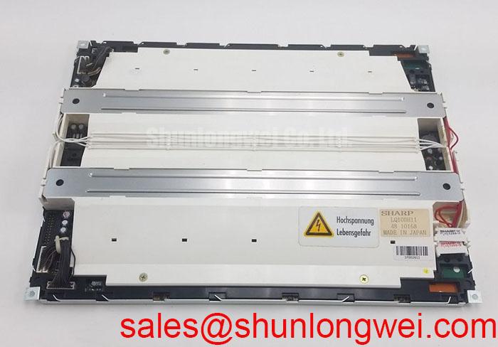
| Product | Sharp LQ10DH11 |
|---|---|
| Category | Industrial Grade LCD/HMI Panel |
| Display Technology | TFT LCD Active Matrix Color Display Module |
| Manufacturer | Sharp |
| Specification Status | Model identification provided; application parameters require verification |
Illuminate the complete screen with a uniform test image, then record whether a vertical hairline remains visible on white, red, green, and blue fields. This three image sequence helps separate a persistent column related defect from a brightness irregularity that appears only under a particular color load. The Sharp LQ10DH11 is identified as a TFT LCD active matrix color display module; the supplied factory data does not define a pixel map, driver construction, or confirmed defect acceptance limit.
Use a known good video source and keep the signal path unchanged during the three color checks. A line that remains in the same screen position across all fields deserves closer inspection at the panel edge, flexible interconnect, and connector seating. A line that changes intensity with the displayed field may instead require investigation of timing, source data, or backlight uniformity. This approach avoids assigning a single cause before the electrical and optical evidence has been compared.
A 45 degree flashlight inspection with the display unpowered can help distinguish a surface or illumination issue from a geometric line in the active matrix area. Move the light across the cover surface without pressing the panel. A reflection, coating mark, or contamination pattern may move with the light, while a fixed image line normally remains registered to the pixel grid. Do not apply localized pressure to the glass or bezel during this check.
When the line appears only after the module warms, compare the screen at cold start and after normal operating stabilization. Record the ambient condition, input source, displayed pattern, and connector state. The result is useful for repair triage, but it is not a field failure rate or a manufacturer acceptance statement. No verified LQ10DH11 backlight lifetime curve or 50,000 hour brightness endpoint is included in the supplied factory information, so a specific MTBF or 50 percent brightness claim should not be assigned to this model.
For incoming inspection, check the panel edge and connector area under magnification for visible contamination, uneven insertion, or mechanical interference. Compare the suspect unit with an approved reference using the same pattern generator and camera exposure. If the defect follows cable movement, stop the test and inspect the interface rather than continuing to flex the display. A replacement evaluation may include the similarly categorized LQ64D341, but physical dimensions, connector mapping, optical characteristics, and electrical timing must be matched independently before any substitution decision.
💡 Bench Tip: Use ESD protection and insert the flat flexible cable squarely to the connector stop before locking it; an uneven insertion can create an intermittent image fault that resembles a panel defect.
Mitigating Gray to Gray Response Time Escalation during Cold Start Machine Power Up
Capture a moving gray scale pattern immediately after power up and compare it with the same pattern after the display has reached the equipment’s normal internal temperature. Look for trailing, incomplete transitions, flicker, or a temporary loss of tonal separation rather than treating every cold image change as a permanent panel failure. The supplied specification identifies the LQ10DH11 as a TFT LCD active matrix color module but does not publish a confirmed gray to gray response time, operating temperature range, contrast ratio, sunlight rating, or coating specification.
Liquid crystal optical behavior can vary with temperature, and the correct evaluation therefore requires controlled conditions and a repeatable image sequence. Log the panel temperature, supply behavior, video source, and time from power application to stable image. If the image remains correct while a cold start produces a temporary response lag, compare the input timing and power sequencing with the original equipment design. If artifacts remain after thermal stabilization, inspect the signal path and connector before attributing the issue to optical viscosity.
Do not identify the LQ10DH11 as an IPS, MVA, anti glare, optically bonded, or sunlight readable panel unless that feature appears in the original panel documentation for the exact part number. Those characteristics affect viewing angle, off axis color shift, reflection control, sealing, and service handling, but they are not established by the factory data supplied here. Sharp’s industrial display resources at Sharp Devices Europe Industrial Display Solutions and the Sharp Display Solutions Official Portal provide useful technology context, while model specific limits remain part of the applicable documentation.
For equipment such as a heavy mining shovel or earthmoving telematics display, the mechanical enclosure, window design, vibration isolation, and thermal path can influence the observed image as much as the panel itself. Treat the LQ10DH11 as a candidate module only after checking the original mounting geometry, viewing direction, connector access, and environmental control. The system integrator should verify whether the target assembly requires optical bonding, perimeter sealing, anti glare treatment, or a particular backlight arrangement.
Cold start testing should also include a visual check for edge haze, uneven illumination, and changes near the bezel. These observations can indicate an enclosure or temperature distribution issue, but they do not establish an internal seal failure without additional evidence. A stable test fixture, controlled image source, and repeated observation provide more useful service information than a single visual inspection performed immediately after storage.
VESA versus JEIDA Data Mapping Alignment and Even Odd Channel Signal Integrity
Probe the panel supply and video interface at the connector during power up, then compare the observed timing and data order with the original LQ10DH11 documentation before changing any wiring. The supplied factory parameter set does not specify logic voltage, resolution, interface type, VESA or JEIDA mapping, pixel clock, power rise time, differential impedance, or channel skew. These values must therefore be treated as system dependent rather than assigned to this model.
A split screen, reversed color order, missing half image, or unstable vertical region can result from incorrect data mapping, channel order, timing, grounding, or connector contact. Check whether the symptom changes when the source pattern changes, and compare the waveform at the source and panel ends when suitable test access is available. A known good signal path is the appropriate reference for deciding whether the issue is mapping related or caused by signal quality.
For a differential display interface, the design consideration is to preserve controlled routing, matched pair geometry, and a continuous return path through the complete cable and board assembly. The actual target impedance, tolerance, skew budget, and termination arrangement must be established by the interface specification and the host board design. Do not apply generic 3.3 volt or 5 volt assumptions to the LQ10DH11. The system integrator should verify the required supply voltage and interface definition from the original panel documentation.
Even and odd channel checks are most useful when performed with a stable test image containing vertical bars, gray transitions, and full screen primary colors. Observe the transition at the panel connector and, where practical, at the source output. A mismatch in data ordering may produce repeatable color or spatial errors, while a marginal connection may produce intermittent changes when the harness is moved. The distinction should be confirmed through repeatable electrical measurement rather than inferred from one screen photograph.
Power sequencing also deserves direct measurement. Confirm that the display supply, enable signals, and video activity occur in the order required by the original system. The correct delay and rise behavior are not provided in the supplied LQ10DH11 specification, so a replacement controller should not be connected solely because its connector appears mechanically compatible. Check pin assignment, keying, cable orientation, and host protection before energizing the assembly.
Use the model’s official category and physical technology as the starting identity: Sharp LQ10DH11, an industrial grade LCD/HMI panel using a TFT LCD active matrix color display module. Resolution, active area, connector arrangement, and optical limits should be populated only from the matching original documentation or a verified engineering drawing.
Shielded FFC and FPC Grounding across Connector Shells
With the equipment de energized, inspect the complete flat cable route from the controller to the LQ10DH11 and verify that the cable is not folded against a sharp edge, trapped by the enclosure, or displaced from its intended strain relief. Pixel jitter and horizontal noise bands should be compared with the motor drive disabled and enabled under controlled conditions, while keeping the display source and supply unchanged.
Shield continuity, connector shell bonding, and return current routing are system level matters. A shield should be connected according to the equipment grounding architecture, with the objective of reducing unwanted common mode coupling without creating an uncontrolled current path through the panel frame. The LQ10DH11 factory information supplied here does not define a shield termination method, cable construction, ferrite requirement, or EMC performance claim.
When a display is installed near a high power variable frequency drive, route the display cable away from switching power conductors where the enclosure permits and maintain a deliberate reference path for the interface return. If a ferrite or common mode component is evaluated, select it from measured interference behavior and the cable’s actual construction rather than treating it as a guaranteed cure. Verify the result with the equipment operating across its relevant speed and load range.
Measure the suspected noise at the display connector and compare it with the controller output. If the disturbance is present at the source, investigate the controller supply, grounding, and drive coupling. If it appears only after the cable is connected, examine shield termination, connector seating, cable orientation, and mechanical routing. This comparative method avoids declaring the panel itself defective from a symptom that may originate elsewhere in the enclosure.
The same principle applies to a 360 degree connector shell or shielded FFC assembly: establish the intended contact surfaces, verify continuity without relying on paint or loose hardware, and confirm that the cable is not carrying mechanical load. Mechanical retention and electrical bonding should be evaluated separately. The system engineer must validate the final arrangement with the actual enclosure, drive installation, cable length, and switching conditions.
For broader integration guidance covering industrial display and HMI design considerations, consult Industrial Display and HMI Solutions. The reference can support enclosure and interface planning, while the LQ10DH11 remains subject to its exact factory documentation, host compatibility, and measured installation results.