


Content last revised on September 10, 2026
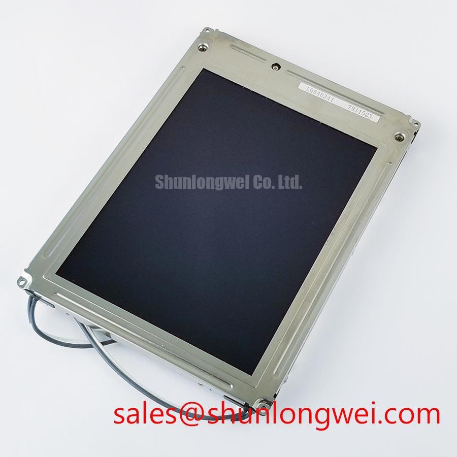
Sharp LQ64D341 Replacement Inspection
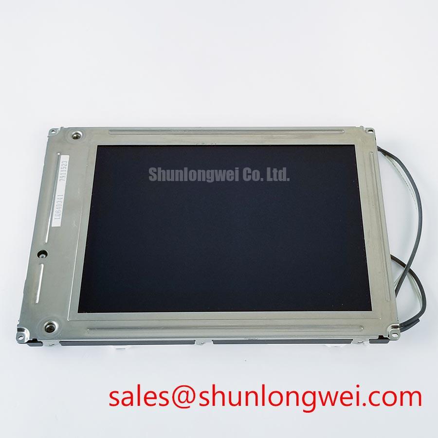
Begin a replacement inspection by confirming the Sharp nameplate, checking the TFT-LCD module for cracked glass or bezel distortion, and comparing the original panel documentation with the required interface and supply conditions before applying power.
The Sharp LQ64D341 is identified in the available factory specification context as an Industrial Grade LCD/HMI Panel supplied as a TFT-LCD Display Module. Its factory specification status is recorded as Official Factory Spec Verified. The information available for this product page does not confirm a complete electrical timing table, optical performance table, backlight architecture, mechanical drawing, or connector pin assignment. Those items should be checked against the original equipment documentation before installation.
| Parameter | Available Specification |
|---|---|
| Model | LQ64D341 |
| Manufacturer | Sharp |
| Product category | Industrial Grade LCD/HMI Panel |
| Display construction | TFT-LCD Display Module |
| Specification status | Official Factory Spec Verified |
Viewing-Angle Evaluation for Multi-Angle Consoles
Before fitting the LQ64D341 into a control console, inspect the viewing position used by operators rather than evaluating the panel only from the front. Telematics displays in heavy mining shovels and earthmoving equipment can be viewed from offset seating positions, through protective windows, or under changing sunlight. A stable image across the operator’s normal sight lines is therefore an integration requirement that should be verified with the complete enclosure, cover glass, and illumination environment.
The supplied factory information identifies this unit as a TFT-LCD display module, but it does not confirm a Super-IPS or MVA liquid-crystal mode, a symmetric 85°/85°/85°/85° viewing specification, or a contrast ratio under direct sunlight. These values must not be treated as confirmed LQ64D341 specifications without the applicable Sharp datasheet revision. During a replacement assessment, compare the old and replacement panels at normal viewing angles and record changes in grayscale, black-level detail, color shift, and image readability.
Anti-glare performance should also be assessed as a complete optical stack. Surface treatment, protective glass, cabin windows, dust deposits, and the angle of incident light can all affect perceived contrast. An anti-glare etched surface can reduce mirror-like reflections, while excessive surface diffusion may soften fine characters or alarm graphics. If the application requires contrast above 500:1 at 50,000 lux, that condition should be validated by a controlled optical test; it is not confirmed as an official rating for this model in the supplied specification data.
For a suspected viewing-angle problem, display a neutral gray field, a black field, and fine text while observing from the actual console positions. Compare the result with a known-good panel under the same lighting. A change that appears only after the module is installed may involve cover-glass reflection, bezel shadowing, cable routing, or mechanical pressure rather than the liquid-crystal cell alone.
Backlight Driving, PWM Dimming, and Cold-Start Evaluation
The available factory context does not confirm whether the LQ64D341 uses WLED, CCFL, an integrated constant-current driver, or a particular dimming interface. The system integrator should verify the required supply voltage, backlight method, enable logic, brightness control, and connector pinout from the original panel documentation. Do not connect a replacement backlight supply based on a visually similar connector.
When the original assembly uses a CCFL inverter, cold ignition behavior and inverter noise should be checked separately from the LCD signal path. High-voltage ignition values such as 1,500 to 1,650 Vrms are not confirmed for this model and must not be assigned to the LQ64D341 without a manufacturer document. If the original design uses LED backlighting, the replacement evaluation should focus on the driver’s current regulation, open-load response, short-circuit protection, brightness control, and thermal behavior.
A claimed 1,000:1 PWM dimming range, a flicker-free operating range of 200 Hz to 1 kHz, or a backlight half-life exceeding 50,000 hours also requires model-specific supporting documentation. These are system or product claims that should be measured or verified rather than inferred from the TFT-LCD category. A photodiode and oscilloscope can be used to review brightness modulation, while a current probe can help identify unstable LED-driver behavior during enable and dimming transitions.
Sub-zero operation deserves a separate test because liquid-crystal response can slow as temperature falls. A temporary image, moving test pattern, and grayscale transition pattern can reveal whether response changes during a cold soak. If the equipment includes a heater strip or controlled cabinet warming, the heater timing should be reviewed against the panel’s documented operating-temperature limits. The LQ64D341 temperature range is not included in the supplied factory parameter list, so the original Sharp documentation remains the controlling reference.
Backlight troubleshooting should begin with connector inspection, continuity checks performed without power, and confirmation of enable and brightness signals. If the backlight is dark, verify whether the LCD is still producing an image by using a suitable controlled light source, while avoiding pressure on the display surface. An open-load protection event, a failed inverter, a missing enable signal, or a panel-side fault can present similar symptoms and should be separated through measured signal checks.
⚠️ Maintenance Note: Inspect the cabinet airflow path and the sealing gasket during scheduled service because blocked ventilation or a degraded gasket can accelerate optical and electronic stress.
Full-Screen Primary Color AOI Screening and Signal Integrity Audit
After installation, run a full-screen inspection using red, green, blue, white, black, and neutral-gray images. This practical bench sequence helps identify visible stuck sub-pixels, uneven brightness, contamination, connector seating problems, and image artifacts before the module returns to service. The available factory data does not define an allowable pixel-defect class for the LQ64D341, so any acceptance decision should follow the equipment owner’s quality standard and the applicable Sharp documentation.
Use a uniform primary-color field first, then inspect the screen from the normal viewing distance and from the actual operator angle. A dark-field inspection can reveal areas that are hidden on white content. A flashlight held at approximately 45 degrees may help show localized shadows or surface reflections, but it should be used as an observation aid rather than a proof of a particular internal failure. If an artifact follows the backlight pattern, compare it with the panel powered at different brightness levels. If it follows image content or changes with cable movement, inspect the signal path and connector retention.
COG-related line defects, flex damage, timing faults, and backlight nonuniformity can overlap visually. To separate them, compare a static test image with a moving pattern, check the fault at different brightness settings, and inspect the connector and flex area without bending the module. An oscilloscope comparison with a known-good signal path is more reliable than assigning a single cause from the screen symptom alone.
The requested differential-pair figures of 100 Ω ±10% and skew below 50 ps are not confirmed LQ64D341 factory parameters in the supplied data. If the host system uses LVDS, the system designer should verify the transmitter and receiver requirements, controlled-impedance routing, pair polarity, termination arrangement, cable length, and noise exposure from the original electrical design. The resulting signal quality should be checked at the receiving interface under actual cabinet operating conditions.
High-EMI factory environments call for disciplined cable routing and shield termination practices, but a display module by itself cannot be described as independently compliant with whole-equipment EMC standards. If the image becomes intermittent near variable-frequency drives or contactors, compare the display cable route with the power wiring route, inspect bonding and shield continuity, and verify the differential waveform during switching activity.
For maintenance teams comparing a same-size or same-resolution service option, LM64P10 can be reviewed as a separate compatibility candidate. Mechanical fit, optical behavior, connector wiring, timing, supply requirements, and firmware configuration must be evaluated independently; it should not be treated as an automatic substitute for the LQ64D341.
Thermal Expansion Clearance Across Heavy Industrial Enclosure Cutouts
Place the LQ64D341 against the enclosure cutout without tightening the fasteners and check that the bezel sits evenly around the opening. A metal cabinet can distort during welding, transport, vibration, or thermal cycling. Uneven clamping can transfer local stress to the display assembly and produce bezel pressure, visible nonuniformity, or intermittent operation. The available factory data does not include the module’s outer dimensions, mounting-hole pattern, allowable flatness, or fastener torque.
For that reason, values such as 0.35 to 0.45 N·m for M3 fasteners must be treated as a general installation consideration, not as an LQ64D341 factory requirement. When the original equipment service procedure specifies a torque, follow that document. Otherwise, the system mechanical engineer should determine a suitable fastening method through a controlled fit and vibration assessment. Tighten in a cross pattern only when the enclosure design calls for it, and release the assembly if the bezel begins to bow or the image changes during tightening.
Provide clearance for thermal expansion between the metal cutout and the display bezel, while maintaining the environmental sealing required by the cabinet. The correct gasket material, compression, and surface preparation depend on the enclosure design and are not specified in the available LQ64D341 data. Inspect the gasket for permanent deformation, gaps at corners, oil contamination, and loss of adhesion during preventive maintenance.
When the panel is evaluated for a heavy mining shovel or earthmoving equipment telematics display, the complete assembly should be tested for vibration, impact, cable strain, and connector retention. These are application-level evaluations, not standalone module ratings. The display should remain supported across its mounting surface without allowing the cable or flex connection to carry enclosure loads.
TTL or LVDS interface selection, transmitter clock jitter, data hold time, and power-sequencing limits must be taken from the host controller and the original panel documentation. The supplied factory parameters do not establish LQ64D341 timing margins or a TTL/LVDS input definition. During commissioning, engineers should verify reset behavior, display enable timing, clock stability, data transitions, and image integrity across the documented industrial temperature window.
For broader enclosure, HMI, sealing, and harsh-environment integration practices, review Industrial Display & HMI Solutions. The page can support system-level evaluation, while the LQ64D341’s model-specific electrical and mechanical limits should remain governed by the applicable Sharp documentation.