

Content last revised on October 5, 2026
PM45502C Circuit Protection & Reliability: Calibrating DC-Bus Operating Voltage Headroom Derating
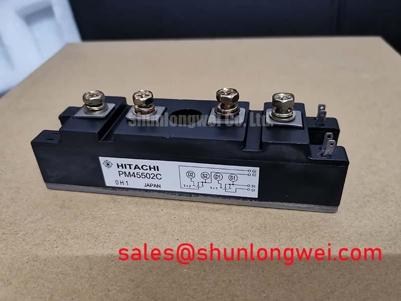
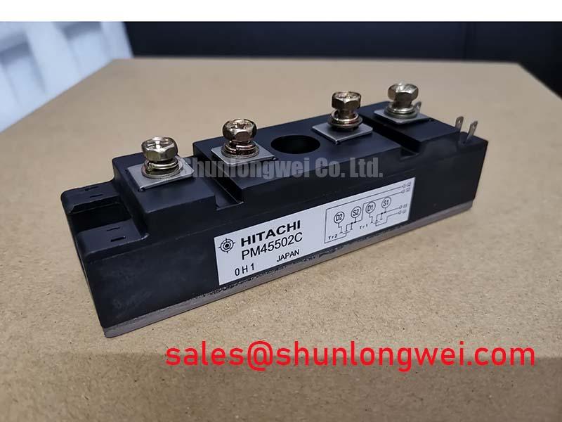
With the DC bus isolated and discharged, compare the installed module’s nameplate and terminal layout with the equipment documentation before removing any connections. For a PM45502C replacement assessment, the supplied official specifications identify a Mitsubishi Electric IPM Module rated at 2500 V and 50 A (Official Specifications). Those ratings establish an initial screening boundary; they do not establish pin compatibility, switching behavior or suitability for a particular inverter.
Start the electrical assessment at the DC link, not at the module’s voltage rating alone. The 2500 V rating (Official Specification) must be compared with the highest voltage the installed equipment can produce, including startup, shutdown, load rejection and regenerative operation. As a Design Consideration, switching overshoot also belongs in that comparison: a bus that remains below the rating in steady operation can still produce a higher voltage at the module terminals during turn-off. The system engineer should establish the required headroom from measured waveforms and the applicable equipment design limits.
For a commercial string inverter or microgrid energy-storage converter, that review may include battery charge transitions and any regeneration or braking path present in the actual schematic. A braking chopper and resistor, where fitted, are system-level energy-absorption elements; the PM45502C rating does not determine their sizing. Check whether the DC-link protection circuit is connected and functioning as documented before attributing an overvoltage trip to the IPM.
Inspect terminal spacing, insulating barriers, contamination and signs of tracking before re-energizing the assembly. Creepage and clearance requirements depend on the equipment’s working voltage, pollution environment, insulation scheme and governing standard; the supplied module data do not establish a universal layout distance. Likewise, altitude-related operating limits and any neutron-induced single-event burnout risk cannot be converted into a PM45502C failure-in-time figure from the voltage rating alone. Treat both as Design Considerations requiring manufacturer evidence and system-specific qualification, rather than assigning a numerical derating or service-life prediction.
When investigating an unexplained protection event, record DC-link voltage at the module terminals during the event, compare the protection input with its known-good behavior, and inspect the busbar and snubber connections. This separates a measured transient from an assumed device fault. Mitsubishi Electric’s power semiconductor information provides manufacturer context for device-family evaluation, but the original equipment documentation remains necessary for PM45502C-specific insulation and protection limits.
Transient Dynamics & Electrical Design: Dynamic Power Loss Dissipation and Multi-R on PM45502C
The 50 A rating (Official Specification) is not, by itself, a permissible pulsed-current profile. During a short overload, junction temperature responds to conduction loss, switching loss, pulse duration and the heat already stored in the assembly. A transient thermal model can represent that response with multiple resistance-capacitance terms, but calculating a peak junction temperature requires the module’s applicable thermal-impedance data and loss characteristics. Neither can be inferred reliably from its voltage and current ratings. As an Engineering Recommendation, use the original PM45502C documentation and measured operating waveforms before approving overload duty.
For an existing converter, capture current, module-terminal voltage and case-temperature trends under the equipment’s normal test procedure. Compare repeated pulses with the cooling interval and operating condition recorded at the same time. A warm case does not directly reveal the instantaneous junction peak; conversely, a brief current excursion does not establish damage without the relevant thermal and protection evidence. Cooling-surface contact and airflow or liquid-cooling performance should be checked against the equipment assembly instructions.
Complementary switching commands need an interlock that prevents both sides of a power leg from conducting together. The required dead time is system-determined: driver propagation delay, turn-off behavior, switching conditions and control timing all affect the margin. Inspect the controller-to-driver signal path and capture actual gate-command timing at the driver when diagnosing an intermittent overcurrent trip. Do not infer adequate dead time from firmware settings alone.
If another module is being considered during equipment repair, compare topology, terminals, mounting, control interface, protection behavior and verified electrical characteristics before treating it as interchangeable. The CM50DY-28H is a separate comparison candidate, not an established direct replacement for PM45502C. Its presence on a parts list cannot substitute for a drawing-level and test-level compatibility review. For background on how switching loss and thermal response relate to IGBT operation, consult The Ultimate IGBT Knowledge Base; equipment-specific life claims still require relevant test data.
PM45502C Thermal-Electrical Optimization: Negative Gate Bias vs Active Miller Clamp Practical Tuning
Examine the installed drive board before selecting a gate-noise remedy. The supplied specifications identify PM45502C as an IPM, but do not establish that its internal gate nodes are externally accessible or that an external negative-bias supply or active Miller clamp can be connected. Applying either technique without the PM45502C interface documentation would turn a general IGBT design principle into an unsupported instruction for this product.
As a Design Consideration, rapid voltage change across a switching device can couple charge through its feedback capacitance and disturb an opposing switch’s gate potential. A low-impedance clamp or a suitable off-state drive strategy may be evaluated where the documented driver interface supports it. The choice depends on the actual gate-drive architecture, isolation arrangement and switching measurements; no negative gate-voltage setting follows from the module’s 2500 V rating. Mitsubishi Electric’s power-device application information offers relevant technology context without establishing a PM45502C gate-drive prescription.
Check the isolation boundary on the existing driver board as part of the same investigation. An optocoupler or digital isolator must withstand the common-mode transients present in its installed circuit, while its propagation behavior must remain compatible with the interlock. Review the specified common-mode transient immunity of the actual isolator and probe both sides of the signal path using an appropriate measurement method. A clean controller command does not prove that the corresponding command arriving at the power stage is clean.
In a system containing another power stage, such as one documented with a CM100DY-12E, map the supply and control boundaries separately. Shared control-board rails or protection signals should be traced on the equipment schematic rather than assumed from the module names. This is particularly useful when a drive-supply disturbance appears only as another converter stage changes state.
Field Diagnostics & Commissioning: Optimizing Gate Drive Loop Geometry to Prevent Oscillation in PM45502C Topologies
Trace the physical return path from the installed driver board to the PM45502C connector before changing control settings. Keep sensitive control returns away from high-current switching paths where the equipment layout permits, and inspect connectors and fasteners for changes that could alter loop impedance. A separate auxiliary emitter or Kelvin return should only be used if the module’s documented terminals provide one; the supplied specifications do not confirm that feature.
As a Design Consideration, minimizing the area of the DC-link switching loop helps limit parasitic-inductance voltage overshoot during turn-off. A laminated or closely coupled bus structure may support that objective, subject to the equipment’s insulation and mechanical constraints. Pro Tip: Compare turn-off voltage at the module terminals before and after any busbar or connection change, then verify the peak against the system’s established voltage limit under representative switching conditions.
For an oscillation complaint, capture the disturbance and establish whether it first appears on the power terminals, the driver supply or the command signal. Compare the result with a known-good operating state while keeping probe connections short and appropriate for the circuit voltage. Ringing at a terminal can have several contributors, including bus geometry, connection condition and drive timing; one waveform alone should not be treated as proof of a single cause.
Before commissioning a repaired converter, confirm the documented terminal mapping, protection wiring, cooling attachment and isolation condition. Where the equipment includes bidirectional battery conversion, test charging and discharging transitions separately because their current paths and thermal duty may differ. Log case temperature and protection activity through the intended operating cycle, and use the equipment maker’s acceptance limits to decide whether the installation is ready for service.