Content last revised on September 13, 2026
Sharp LQ150X1LG81 Viewing Direction, Grayscale Inversion, and Installation Alignment
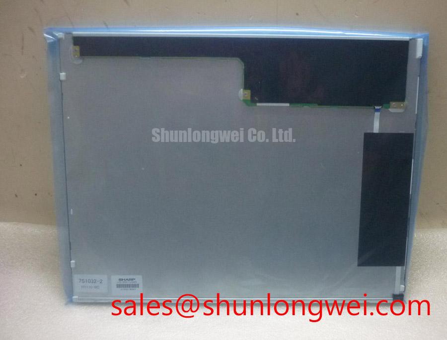
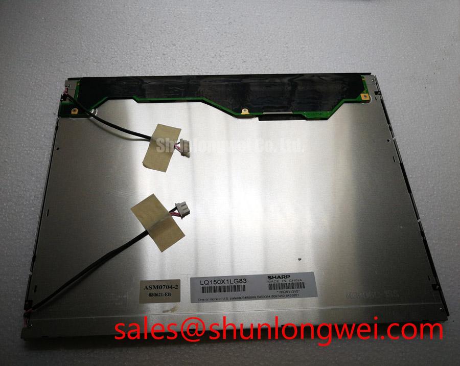
The Sharp LQ150X1LG81 is identified in the supplied factory information as an Industrial Grade LCD/HMI Panel in a TFT-LCD Display Module format. The available official factory data confirms the manufacturer, product category, enclosure format, and factory specification status, but it does not confirm the panel’s electrical timing, optical performance, interface pinout, backlight architecture, or mechanical drawing. Those details must be verified against the original panel documentation before installation.
| Parameter | Factory Information Available for LQ150X1LG81 |
|---|---|
| Manufacturer | Sharp |
| Product category | Industrial Grade LCD/HMI Panel |
| Module format | TFT-LCD Display Module |
| Specification status | Official Factory Spec Verified |
| Electrical interface | Verify from the original panel documentation |
| Backlight configuration | Verify from the original panel documentation |
| Mechanical dimensions and mounting | Verify from the original panel documentation |
For a replacement evaluation, begin with the optical installation rather than assuming that a panel with the same nominal diagonal size will provide identical image behavior. If the panel uses normally white TN technology, it can show grayscale inversion when viewed away from its preferred axis. This is a viewing-direction characteristic that affects whether intermediate gray levels remain visually ordered, especially when an operator looks upward, downward, or from the side of a cabin-mounted HMI.
The correct field check is to display several gray ramps, fine text patterns, and alarm colors while observing the screen from the actual operator position. Repeat the check with the display tilted through the expected enclosure angle. If gray steps reverse, flatten, or become difficult to distinguish, the issue may be viewing-axis alignment rather than a failed panel. Designers should verify the original Sharp panel’s viewing direction and compare it with the mechanical angle of the replacement installation.
TN behavior should not be assessed using IPS or MVA expectations. Those panel families can offer wider and more symmetrical viewing cones, but their optical behavior is not evidence of the characteristics of the LQ150X1LG81. The supplied factory data does not state a viewing-angle specification, contrast ratio, luminance value, or grayscale inversion limit for this model. Claims such as symmetrical 85° viewing performance or stable contrast above a specific value under direct sunlight therefore require a controlled measurement from the applicable datasheet or a sample evaluation.
Ambient light is a separate integration issue. A glossy front surface can produce reflected images that obscure warning messages even when the LCD itself is operating correctly. An anti-glare surface treatment can reduce specular reflection, but it may also alter perceived sharpness, black level, and image texture. The system integrator should verify whether the original module uses an anti-glare or anti-reflective treatment, and should assess the complete display behind its bezel, protective window, and cabin lighting.
For a potential heavy mining shovel or earthmoving equipment telematics display, the practical evaluation should include sunlight entering through the operator enclosure, dust on the cover window, vibration during machine movement, and viewing from a seated or standing position. These are system-level conditions, not factory guarantees for this panel. A same-size or same-resolution candidate such as LMS700KF01-001 should be compared using the same image patterns and viewing geometry rather than selected by size alone.
Backlight Inverter and Ignition Debugging
The backlight arrangement is not confirmed in the available factory parameter set, so the LQ150X1LG81 should not be connected to an inverter or LED driver based only on its model number. The system integrator should verify the required backlight technology, connector assignment, lamp or LED electrical limits, enable signal, brightness control method, and protection behavior from the original panel documentation.
If the removed assembly is connected to a dual-channel CCFL inverter, cold ignition should be investigated as a high-voltage subsystem issue. An inverter that produces audible buzz, repeated restart attempts, uneven illumination, or delayed striking may be responding to lamp aging, connector contamination, insulation stress, transformer loading, or control-loop instability. These observations do not identify one failed component by themselves. Disconnect power, allow the inverter to discharge according to the equipment service procedure, and inspect the complete harness before making resistance or insulation measurements.
Do not substitute a constant-current LED driver for a CCFL inverter without confirming the backlight construction and control interface. Likewise, a PWM dimming specification from an LED driver cannot be assigned to this Sharp module unless it is stated in the panel documentation. The same caution applies to ignition voltage, lamp current, dimming ratio, and claimed service life. None of those values are included in the supplied official factory parameters for LQ150X1LG81.
High-frequency equipment near the display can expose weaknesses in cable routing and grounding. Servo drives, switching power converters, contactors, and inverter-fed motors can inject common-mode noise into the backlight harness or video cable. As a Design Consideration, keep high-voltage backlight wiring physically separated from low-level video and touch-control wiring, avoid unnecessary cable loops, and provide a controlled return path through the equipment chassis. The final arrangement should be validated during switching operation with the enclosure, harness, and display installed together.
For LVDS-equipped systems, the connector pinout, pair assignment, termination arrangement, signal polarity, and data format must be confirmed from the original documentation. A nominal differential impedance target or a particular skew limit is not an official parameter for this model in the supplied data. Engineers should measure the known-good signal path and use oscilloscope verification to investigate intermittent pixels, line noise, or image dropouts. JEIDA and VESA mapping should also be checked before changing a transmitter board, because a format mismatch can produce incorrect colors or unstable image content without physical damage to the LCD.
The related LQ150X1LG11 can be reviewed as a separate Sharp display reference when examining a broader display and backlight topology. It should not be treated as an automatic electrical substitute for the LQ150X1LG81 without a documented interface and mechanical comparison.
Constant Luminance Control and Backlight Reliability Verification
When evaluating a replacement display for industrial HMI service, record luminance uniformity at startup and after the panel reaches a stable operating condition. Inspect the center, corners, and narrow edge regions for visible bands, dark zones, or local bright areas. These observations can result from the backlight, optical stack, driver regulation, bezel pressure, or installation geometry, so the display module and its driver should be tested as a complete assembly.
The factory information supplied for LQ150X1LG81 does not state a luminance rating, LED half-life, L70 value, B50 distribution, MTBF, or thermal resistance. Such figures must not be presented as model-specific specifications without an applicable Sharp datasheet or qualified test source. A claimed operating life above a particular number of hours also requires defined temperature, drive current, duty cycle, luminance criterion, and failure-distribution conditions.
As a Design Consideration, the enclosure should avoid pressing on the active area or trapping heat along the display edges. If a separate heat-spreader rail is used, its position, contact pressure, electrical isolation, and thermal path should be determined by the system engineer after reviewing the panel drawing. Do not invent an internal optical material or assume that a particular diffuser, guide plate, or adhesive is present inside this model.
Backlight troubleshooting should separate open-circuit and short-circuit behavior. An open condition may lead the driver to stop, retry, or report a protection event, while a short or excessive load may trigger current limiting or overvoltage protection. The observed response depends on the external driver design and is not proof of the LCD module’s internal condition. Check the driver output only with measurement equipment and procedures suitable for the relevant backlight voltage, then compare the result with the original assembly’s service data.
Touch functionality also requires careful boundary control. The supplied official information identifies a TFT-LCD Display Module, but it does not confirm an integrated resistive or capacitive touch layer, glove sensitivity, water rejection, controller IC, or touch interface. If the equipment uses a separate industrial touch overlay, verify its controller, connector, calibration method, cover-window thickness, and sealing arrangement independently. Gloved operation and wet-finger response should be tested on the finished enclosure, since mounting pressure, grounding, protective windows, and cable routing can change touch behavior.
Design Tip: Keep video differential pairs consistently routed through the enclosure and validate image stability with the servo system switching at its highest normal interference condition.
For a structured system review, the Industrial Display & HMI Solutions resource provides broader context for enclosure, interface, and harsh-environment evaluation; it does not replace the Sharp model-specific electrical documentation.
High-Humidity Storage Margins and Delamination Prevention
Storage and installation checks should begin with the display’s environmental history. A panel kept in a humid warehouse, moved between cold and warm areas, or installed before condensation has cleared can develop temporary optical haze, connector contamination, or mechanical stress at the bezel and cover interface. The supplied factory information does not specify a humidity profile, storage temperature range, operating temperature range, sealant construction, or delamination qualification for LQ150X1LG81.
Do not assign a 60°C and 90% relative humidity test condition, a −30°C to +85°C operating window, or any thermal-cycle endurance claim to this model unless those values are confirmed by the applicable Sharp specification. These conditions may be useful as system-level evaluation points when required by the equipment owner, but they are Design Considerations rather than factory ratings in the data provided here.
At low temperature, liquid-crystal viscosity can increase and visible response can become slower. A slow gray transition should be evaluated using moving test patterns, the original timing controller, and a temperature record. It may also be related to drive timing, signal integrity, frame rate, or backlight perception. The correct diagnostic method is to compare the panel with a known-good assembly under the same thermal condition rather than assigning a single cause from visual symptoms.
Humidity testing should include inspection of the perimeter, bezel interfaces, cable exits, and protective window. Look for haze, edge lift, bubbles, color changes, or local nonuniformity after the module returns to room conditions. If an enclosure uses a sealant or gasket, its compatibility, compression, cure condition, and long-term stability must be verified by the system designer. The internal adhesive and optical construction of the Sharp module are not stated in the supplied factory data and should not be inferred.
Clock stability and data hold behavior must be checked across the actual operating temperature window specified for the complete equipment. The panel transmitter, receiver, timing controller, cable, and grounding arrangement work as one signal path. If image tearing, intermittent lines, or startup failure appears only at temperature, capture the clock and data signals at the panel interface, confirm power sequencing from the original documentation, and compare timing margins with a known-good unit. The required supply voltage, enable sequence, and reset behavior must be taken from the original panel documentation rather than guessed.
During replacement, preserve the original connector orientation and cable bend path, prevent the frame from twisting against the enclosure, and verify that the bezel opening does not obstruct the active viewing area. Final acceptance should cover image integrity, backlight response, touch operation where applicable, operator viewing angle, and behavior during the equipment’s normal electrical and environmental conditions.