




Content last revised on September 30, 2026
Check Display Signals and Power Sequencing Before Replacing the Panel
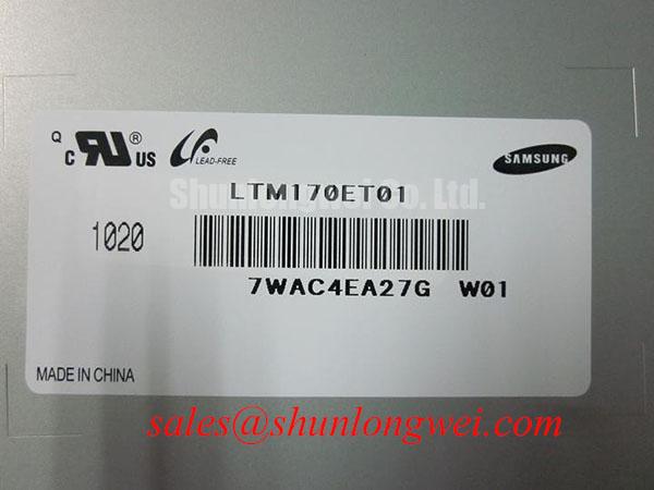
| Model | LTM170ET01 |
|---|---|
| Manufacturer | Samsung |
| Product category | LCD panel |
| Module construction | TFT LCD active matrix color display module |
Probe the display supply at the connector while the HMI starts, then compare its rise and fall with the controller’s display enable signal. A white screen, intermittent image or split picture does not, by itself, establish that the LTM170ET01 has failed. The system integrator should verify the required supply voltage, connector pin assignments and power sequence from the original panel documentation and equipment schematic. Measure at the panel end of the cable: a sound reading at the power board can conceal a drop across a loose connector or damaged conductor.
With power isolated, inspect the display cable for an incompletely seated latch, skewed insertion, contaminated contacts and a sharp fold beside the connector. Flexible cable routing deserves particular attention on a serviceable HMI door. Repeated opening can concentrate bending at one point even when the cable looks undamaged across its wider span. Preserve the installed bend path during a trial fit and keep the connector strain relief from pulling on the contact area when the enclosure closes.
⚠️ Field Alert: Disconnect equipment power before releasing or inserting the display connector.
For an unstable picture, capture the clock and data activity at an accessible test point and compare it with a known working signal path, if the equipment provides one. This is a Design Consideration, not a published interface specification for the LTM170ET01: differential impedance, transmitter type and data mapping must follow the documented controller and panel interface rather than an assumed LCD convention. If color channels are exchanged or part of the image is displaced, check the cable orientation and the controller’s configured mapping before treating the glass as defective.
Separate image formation from illumination during the same startup capture. An image that is faintly visible under directed light calls for checks of the backlight supply, driver enable and brightness control path; it does not prove that the backlight itself is the sole fault. If a replacement panel is being evaluated, compare the original unit’s connector, mounting envelope, electrical interface and illumination connections as separate acceptance items. The LQ10D131 is another display model for a documented comparison, not an established drop-in replacement for the LTM170ET01.
Inspect Storage Exposure, Temperature Effects and Edge Stress
Examine the panel perimeter for moisture marks, lifted layers or disturbed seals before energizing a unit taken from storage. Record the storage conditions and allow the assembly to reach a stable workshop temperature before judging an optical defect. A patch that changes as the equipment warms may involve the illumination path, mechanical pressure or temperature-dependent liquid-crystal behavior; visual appearance alone cannot distinguish them.
The LTM170ET01’s manufacturer identification and TFT LCD construction do not establish a storage humidity limit or operating temperature range. For a CNC operator panel or robot teach pendant under evaluation, use the original panel documentation and the equipment’s environmental requirements to set the test conditions. Avoid transferring a temperature rating from the host machine, enclosure or another display to this module. As a Design Consideration, check that an enclosure gasket and any condensation-control provisions protect the complete installed assembly under the intended conditions.
At low ambient temperature, compare response to the same moving test image after the panel has stabilized and after it has warmed. Slower transitions can be consistent with temperature-sensitive LCD behavior, but controller timing and illumination should be checked alongside them. At the other end of the equipment’s temperature range, inspect whether bezel expansion changes pressure near the visible area or strains the connector. Assessing both optical behavior and cable retention during a controlled temperature test is more useful than assigning a temperature-related fault from a single photograph.
If the display develops intermittent lines only while a cabinet fan, spindle or nearby mechanism operates, observe the signal and supply at the panel connector during that event. Vibration can expose a marginal connection without leaving a permanent mark. Reseat only after power is isolated, verify that the latch closes evenly, and repeat the observation without holding the cable in place by hand. For broader enclosure and environmental test planning, Industrial Display & HMI Solutions provides a system-level reference; acceptance limits still need to come from the particular equipment and panel documentation.
Fit the Bezel Without Loading the Active Display Area
Place the unpowered LTM170ET01 in the intended opening and check where the bezel or gasket contacts the module before tightening any retainers. A dark patch near an edge can result from local pressure, but the backlight and displayed image must also be examined before assigning a cause. The assembly should support and retain the module through its documented mounting features, not through pressure on the visible display area.
Do not choose a fastener torque from the screw size alone. The permissible fastener, torque, support points and opening dimensions require the module drawing and the host assembly instructions. As a Design Consideration, tighten retainers progressively while watching for changes in edge uniformity, and use a gasket arrangement that accommodates enclosure movement without bowing the panel. The final compression and shock-isolation method are system-design decisions to verify in the assembled enclosure.
Check the cable after the display is secured, not just during the loose bench fit. A connector that sits squarely with the module on a table may be pulled sideways when a rear cover, cable clamp or hinged panel is installed. Confirm that the cable clears adjacent metalwork throughout the equipment’s normal movement and that service access will not require it to be creased at the connector. This is especially important when comparing a candidate panel for a cramped operator station: matching the visible opening does not establish mechanical or electrical compatibility.
An optical inspection should distinguish a mark that moves with bezel pressure from one that persists when the module is supported without that pressure. Remove and refit the bezel using the equipment’s approved procedure, then repeat the same image and brightness settings. Do not press directly on the display to reproduce a defect. Liquid-crystal image formation depends on the panel’s optical stack; the general relationship between the display and its polarizers is described in Liquid-crystal display optics. That background does not identify the internal materials used in this particular module.
Screen Primary Colors, Uniformity and Backlight Control Separately
Display full-screen red, green and blue images from a known working source, then inspect each image for persistent points, missing color regions and fixed lines. Follow with a uniform dark image and a uniform light image to check background consistency. Keep the viewing position, enclosure state and brightness setting consistent between observations, and record defects by location so a repeat test can determine whether they are fixed or intermittent.
For a screen that appears black, shine a flashlight obliquely across the powered display and look for a faint image while checking the backlight control signal and driver supply. This is a diagnostic comparison, not a definitive test of an internal failure. A visible faint image directs attention toward illumination and its control path; an absent image calls for continued checks of panel power and video activity. Fixed vertical or horizontal lines warrant inspection of the cable and source signal before drawing conclusions about inaccessible panel connections.
If brightness changes cause flicker or audible noise, observe the host’s dimming waveform and the backlight supply under the same screen conditions. No dimming frequency, duty-cycle range or backlight-life figure is established here for the LTM170ET01. Compare measured behavior with the original equipment documentation and test any proposed change at the assembled-system level. Mini-LED backlight architecture describes a different illumination approach; it should not be taken as a description of this module’s backlight.
Leave a static HMI page on screen only for the duration needed to reproduce a reported residual image, then switch to varied content and document whether the mark changes. Static interface artwork, illumination nonuniformity and a persistent source-image fault can look similar in a quick inspection. The practical handoff record should identify the test pattern, brightness state, warm-up condition, cable position and whether the defect remained after the source image changed. Those observations give a repair engineer a reproducible basis for deciding what to measure next.