



Content last revised on September 19, 2026
Transient Dynamics & Electrical Design: Thyristor Commutation Current on MCC200-16IO1
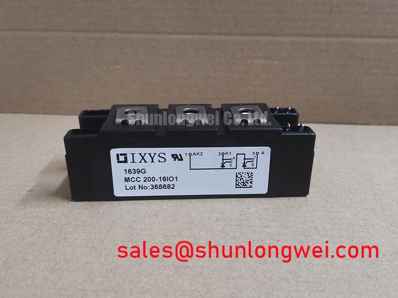
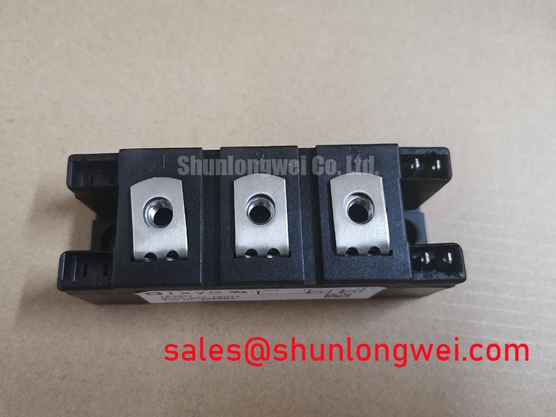
Verify the module nameplate and terminal designations against the controlled equipment documentation before connecting any test source. The MCC200-16IO1 is an IXYS dual thyristor module with an official repetitive peak off-state and reverse voltage rating of 1600 V and a rated current of 200 A, supplied in a module housing. These ratings define the electrical identity that must match the failed assembly before a repair decision is made.
The part number identifies a thyristor module, so diode reverse-recovery current, recovery softness, IGBT desaturation protection, and gate turn-off drive language must not be applied to this device as though they were published MCC200-16IO1 characteristics. The system integrator should obtain the controlled IXYS datasheet for the exact internal circuit, terminal arrangement, gate trigger limits, latching current, holding current, surge-current capability, fuse coordination data, and mounting requirements. Those values are not established by the 1600 V and 200 A ratings alone.
In a phase-controlled rectifier, commutation behavior is determined by the entire transformer, busbar, load, line impedance, firing sequence, and any companion diode path. A Design Consideration is to capture voltage and current waveforms at the module terminals during representative commutation events, then compare peak electrical stress with the applicable official ratings. Keep the power loop compact and geometrically balanced to reduce inductive voltage excursions during current transfer. The physical basis for resistive heating in conductors is described in Joule heating, which is relevant when assessing busbar temperature rise near a high-current semiconductor module.
For an alternative reference during a controlled compatibility review, PD25016A can be compared only after its circuit configuration, voltage class, current ratings, terminal layout, thermal interface, and triggering requirements have been verified against the original equipment documentation.
Assembly Integrity & Layout Architecture: Ensuring Uniform Heatsink Contact Pressure for MCC200-16IO1
Before fitting the MCC200-16IO1, inspect the heatsink contact area for flatness, residue, corrosion, raised burrs, and localized damage that could prevent uniform baseplate contact. The module’s 200 A official current rating does not remove the need to validate the thermal path under the actual duty cycle. Junction-to-case thermal resistance, permitted case temperature, mounting torque, and thermal compound guidance must be taken from the controlled manufacturer documentation for this exact module.
Apply thermal interface material as a thin, continuous layer using the specified assembly method, then tighten mounting hardware in a staged cross pattern. This is a Design Consideration intended to distribute clamp force without bending the housing or creating a contact-pressure bias across the baseplate. Use only the official mounting-hole details and torque limit for this module. A torque value associated with another package or another fastener size is not an MCC200-16IO1 specification.
Pro Tip: Tighten the module mounting hardware progressively in a cross pattern and verify the finished busbar and heatsink assembly is mechanically unstressed before energizing the rectifier.
Power connections should reach the designated terminals without forcing the module body or imposing constant side load on its terminals. Busbars should be supported independently and arranged to preserve equal current paths where the circuit topology requires it. In a green hydrogen electrolyzer DC power rectifier, designers should verify contact resistance, conductor temperature, cooling performance, and current sharing using measurements from the installed cabinet rather than assumptions taken from a nominal module rating.
When a separate controlled rectifier or auxiliary power stage is present, the SKKT 106B14E is a related power-semiconductor reference for topology review. Its presence in a design does not establish interchangeability with the MCC200-16IO1, because device function and connection requirements must be checked at circuit level.
Preventing Spurious Faults: Gate-Firing Pulse-Train Timing Guidelines for MCC200-16IO1
With the main supply isolated and discharge procedures completed, trace each gate and cathode control lead from the firing board to its specified MCC200-16IO1 terminal. Confirm connector retention, conductor condition, insulation clearance, and polarity against the original schematic. A thyristor gate is a trigger input, not an IGBT gate that is held under continuous voltage control; firing-board behavior must therefore be assessed using the official trigger, latching, and holding parameters for this specific module.
Gate-pulse rise time, pulse width, repetition strategy, isolation barrier performance, and phase-reference integrity are system-dependent. An Engineering Recommendation is to examine trigger pulses at the module terminals under safely controlled operating conditions, using an appropriate isolated measurement method. Compare their timing and amplitude with the controlled module datasheet and the equipment firing-board specification. A pulse that appears correct at the controller output can be altered by lead inductance, common-mode disturbance, poor return routing, or a damaged interface connection.
Use short paired gate and return conductors where the equipment architecture permits, and keep these control paths separated from high-current busbars. This is a Design Consideration to reduce unwanted coupling into the firing circuit. Designers should validate gate timing across the real operating current range, particularly where multiple thyristor positions must share a programmed phase relationship. Avoid assigning a single cause to missed firing, uneven load current, or unstable output voltage; each symptom can arise from control timing, source impedance, power connections, thermal conditions, or the load itself.
For broader guidance on gate-drive observation, thermal-path checks, and power-loop integration, consult IGBT Design & Integration. The integration principles concerning measured switching behavior and low-inductance layout are useful context, while thyristor-specific limits remain governed by the MCC200-16IO1 documentation.
MCC200-16IO1 Circuit Protection & Reliability: Calibrating Surge Energy Dissipation and Clamping Voltage
Confirm the measured line environment, transformer configuration, AC input protection architecture, and intended thyristor topology before selecting or adjusting surge suppression parts around the MCC200-16IO1. The module’s official 1600 V rating is a device boundary, not a complete surge-protection design. Metal-oxide varistors, RC snubbers, fuses, contactors, transformers, busbars, and control timing interact during abnormal events, so their selection must be validated at system level.
As a Design Consideration, place surge-control elements so that the protected circuit sees minimal added connection inductance, while preserving service access and required clearances. The system engineer should confirm clamp behavior with measured transient waveforms and verify peak voltage margins against the module’s official blocking-voltage rating. Where an installation is evaluated against IEC 61000-4-5 surge conditions, compliance belongs to the completed equipment and its defined test configuration, not to the thyristor module as an independent certified system.
Fuse selection requires the manufacturer’s applicable I2t coordination data, the measured prospective fault current, semiconductor protection requirements, and the upstream protection arrangement. Do not infer an acceptable fuse from the 200 A current rating. Review the equipment schematic, applicable fuse documentation, and the MCC200-16IO1 datasheet together before changing protection parts.
For neutral context on available power semiconductor and diode product families used in rectification-related equipment, see Shindengen Power Semiconductor Modules & Diodes. Any evaluation of another component must verify its official electrical, mechanical, thermal, and control-interface requirements against the installed MCC200-16IO1 circuit.