

Content last revised on October 9, 2026
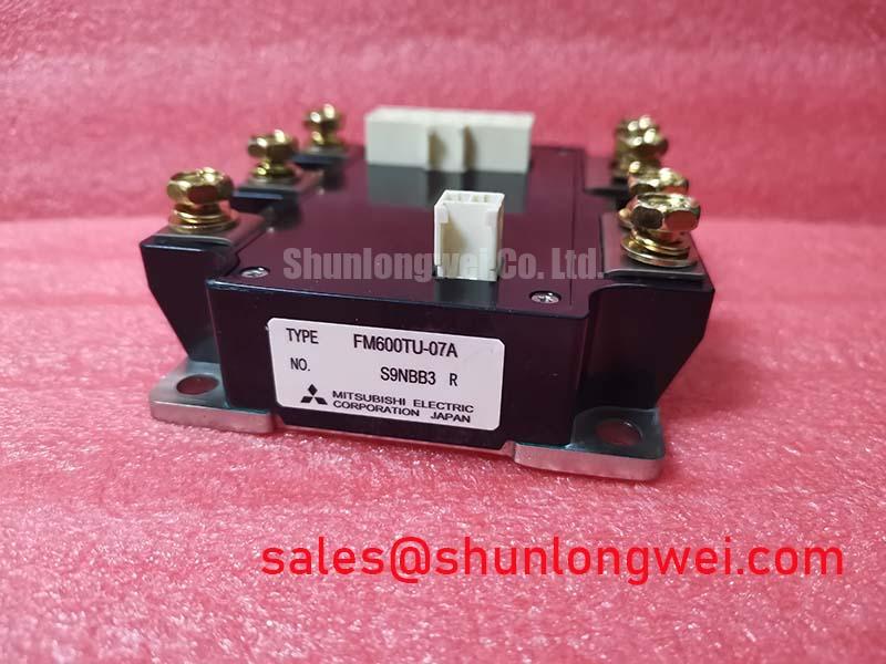
Assembly Integrity & Layout Architecture: Implementing Multi-Module Parallel Current Sharing for FM600TU-07A
Start a parallel-module assessment with the circuit diagram and terminal assignment, rather than assuming that matching model markings establish electrical interchangeability. Inspect the mounting surface, terminal seating, and busbar alignment. Mechanical stress from misaligned conductors can compromise an otherwise consistent assembly; mounting hardware and tightening requirements should follow the applicable manufacturer drawing.
Design Consideration: Static current sharing depends on conduction characteristics at the actual operating current and junction temperature. A positive temperature coefficient of on-state voltage can assist sharing in certain operating regions, but it must not be attributed to FM600TU-07A without its characteristic curves. Compare devices under controlled conditions and account for cooling differences before accepting parallel operation.
Dynamic sharing requires comparable gate-loop impedance, power-path inductance, and driver timing. Designers should evaluate symmetrical routing and individual gate damping against measured switching waveforms. Establish conductor clearances from working voltage, insulation requirements, and the equipment’s applicable standard—not from the module name. The CM100DY-12E provides another reference for a specification comparison, but neither equivalent ratings nor replacement compatibility should be assumed.
💡 Bench Tip: Use ESD precautions and a consistent cold-state reference when comparing terminal readings, and never move probes or gate connections while the power stage is energized.
Field Diagnostics & Commissioning: Cosmic Ray Robustness and Voltage Derating in FM600TU-07A Topologies
For incoming inspection, use diode mode only after the documented internal circuit establishes which terminal pairs contain a diode path. Compare forward and reverse readings with a known-good reference under identical conditions. Unexpected conduction warrants further isolation and testing; a handheld meter alone cannot establish blocking capability, switching performance, or insulation integrity.
Design Consideration: Cosmic-ray susceptibility and altitude-related reliability require device-specific evidence. No FM600TU-07A failure-in-time rate, single-event burnout limit, or altitude derating factor is established here. A blocking-voltage rating alone cannot support such a calculation. For an installation requiring this assessment, request applicable manufacturer reliability guidance through Mitsubishi Electric Power Semiconductors & High-Power Modules.
During controlled commissioning, assess driver source and sink capability against documented gate-charge and switching conditions. External gate resistance should be selected through waveform validation, balancing ringing suppression against switching loss and protection response. If the equipment uses a bootstrap supply, verify its recharge opportunities, voltage droop, and diode recovery behavior over the commanded operating range; these are driver-system checks, not confirmed module features.
Assembly Integrity & Layout Architecture: Implementing Overvoltage Trip Prevention for FM600TU-07A
Investigate an overvoltage trip by measuring the DC-link behavior and checking the equipment’s energy-return path. Distinguish a sustained bus-voltage rise from a local switching overshoot using suitable probes and measurement bandwidth. These observations guide separate checks of the energy-handling circuit and commutation layout without assigning one cause to every trip.
Design Consideration: Where the equipment contains a braking chopper, its switching device and resistor require evaluation against returned energy, duty cycle, thermal capacity, and protection coordination. An internal braking switch is not established for FM600TU-07A. Motor-deceleration braking also should not be presumed relevant to an inverter welder or induction-heating supply; inspect the actual topology first.
For industrial inverter welder and medium-frequency induction-heating compatibility assessments, verify switching frequency, cooling, terminal arrangement, and drive requirements against the original equipment documentation. A separate device such as CM50DY-28H may enter the same system-level review, but its circuit role and compatibility require independent confirmation.
FM600TU-07A Circuit Protection & Reliability: Calibrating PCB Gate Loop Layout Symmetry
Trace the gate-driver return through the schematic and physical assembly. Do not assume a dedicated Kelvin return terminal exists. Where the documented connection permits it, separating the driver reference from the high-current return can reduce shared-inductance disturbance. Verify gate waveforms at the device terminals rather than relying solely on measurements at the driver board.
Design Consideration: Negative off-state bias, desaturation detection, and soft shutdown require coordination with confirmed gate limits and short-circuit capability. No short-circuit safe operating area is established here. Protection thresholds, blanking, and shutdown timing should therefore come from supported device data and validated equipment requirements. Manufacturer technology context is available through Mitsubishi Electric Global Semiconductor Device Technologies.
Keep insulation testing separate from semiconductor blocking tests: neither a blocking-voltage rating nor a diode-mode reading establishes terminal-to-baseplate withstand. Use documented test voltage, duration, terminal grouping, and leakage criteria. The Field Engineer’s Handbook offers broader diagnostic context; the acceptance record should retain the actual readings, test conditions, and applicable equipment limits.