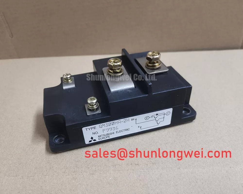
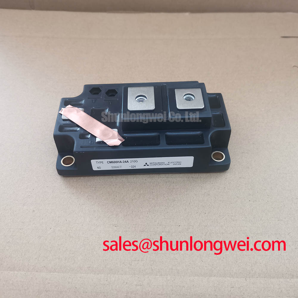
Content last revised on January 6, 2026
MG50Q2YS50 IGBT Module: An Engineer's Reference for Motor Control Applications
The Toshiba MG50Q2YS50 is a GTR module engineered for robust performance in high-power switching and motor control systems. This device integrates a full half-bridge configuration into a single, electrically isolated package, streamlining thermal management and assembly. With core specifications of 1200V | 50A | VCE(sat) 3.6V (Max), it provides a solid foundation for power conversion efficiency and durability. Key benefits include a low saturation voltage for reduced conduction losses and fast switching times to minimize energy dissipation during transitions. The module directly addresses the need for a compact, high-voltage switching solution in demanding industrial environments. For three-phase AC motor drives requiring a balance of voltage headroom and moderate current handling, the MG50Q2YS50 offers a well-defined operational profile.
Key Parameter Overview
Decoding the Specs for Industrial Power Conversion
The technical specifications of the MG50Q2YS50 are tailored for designers of industrial inverters and motor drives. The parameters below highlight its capacity for efficient power handling and switching performance under typical operating conditions.
| Characteristic | Symbol | Test Condition | Min | Typ | Max | Unit |
|---|---|---|---|---|---|---|
| Absolute Maximum Ratings (Ta = 25°C) | ||||||
| Collector-Emitter Voltage | VCES | - | - | - | 1200 | V |
| Gate-Emitter Voltage | VGES | - | - | - | ±20 | V |
| Collector Current (DC, Tc=80°C) | IC | - | - | - | 50 | A |
| Collector Current (Pulsed, 1ms) | ICP | Tc=80°C | - | - | 100 | A |
| Collector Power Dissipation | PC | Tc = 25°C | - | - | 400 | W |
| Junction Temperature | Tj | - | - | - | 150 | °C |
| Electrical Characteristics (Ta = 25°C) | ||||||
| Collector-Emitter Saturation Voltage | VCE(sat) | IC = 50A, VGE = 15V | - | 2.8 | 3.6 | V |
| Fall Time | tf | VCC=600V, IC=50A, VGE=±15V | - | 0.1 | 0.3 | µs |
| Turn-off Delay Time | td(off) | Inductive Load | - | 0.5 | - | µs |
| Diode Forward Voltage | VF | IF = 50A, VGE = 0 | - | 2.4 | 3.5 | V |
| Thermal Resistance (IGBT) | Rth(j-c) | Transistor Stage | - | - | 0.31 | °C/W |
The parameters listed are based on the official Toshiba datasheet. For comprehensive details, including performance curves and test circuits, please refer to the complete document.
Download the MG50Q2YS50 datasheet for detailed specifications and performance curves.
Application Scenarios & Value
System-Level Benefits in AC Motor Drives and Power Converters
The MG50Q2YS50 is optimized for mid-power applications where high voltage blocking capability is a primary requirement. Its 1200V VCES rating provides a substantial safety margin for systems operating on 400V or 480V AC lines, making it a suitable component for industrial Variable Frequency Drive (VFD) systems. A key engineering challenge in VFD design is managing the transient voltage spikes that occur during switching. The MG50Q2YS50's high voltage rating directly mitigates this risk, enhancing system reliability.
Its 50A continuous collector current rating at a case temperature of 80°C positions it well for controlling AC induction motors in the 15 kW to 22 kW range. The module's thermal resistance (Rth(j-c)) of 0.31 °C/W for the IGBT is a critical parameter for thermal design. Think of thermal resistance as the insulation on a pipe; a lower value means heat can escape more easily from the semiconductor junction to the heatsink. This efficiency in heat transfer is crucial for maintaining the junction temperature within safe limits, especially under heavy load conditions found in applications like industrial pumps, fans, and conveyor systems. While the MG50Q2YS50 is well-suited for these tasks, for applications demanding higher current capabilities, the related MG150Q2YS50 offers a similar voltage rating with a significantly higher current capacity.
Frequently Asked Questions (FAQ)
What is the primary benefit of the MG50Q2YS50's half-bridge configuration?
The integrated half-bridge design, containing two IGBTs in a common emitter configuration, simplifies the power stage layout for single-phase or three-phase inverters. This reduces stray inductance compared to using discrete components, which can lead to lower voltage overshoot and improved switching performance. It also streamlines the assembly process and thermal management by providing a single, flat baseplate for mounting to a heatsink.
How does the VCE(sat) of 3.6V (Max) impact system efficiency?
The Collector-Emitter Saturation Voltage, or VCE(sat), is the voltage drop across the IGBT when it is fully turned on. This voltage directly contributes to conduction losses (Power Loss = VCE(sat) x Collector Current). A lower VCE(sat) means less power is wasted as heat during the on-state, which improves overall system efficiency and reduces the cooling requirements for the heatsink, potentially allowing for a more compact and cost-effective thermal solution.
Engineer's Perspective
From an engineering standpoint, the Toshiba MG50Q2YS50 represents a practical, no-frills solution for established industrial applications. Its specifications indicate a focus on reliability and core performance within the demanding voltage range of 400V-class systems. The combination of a 1200V rating and a 50A current capacity in an industry-standard package provides designers with a component that is straightforward to implement and thermally manage. It is a workhorse module designed for longevity in applications where operational uptime is paramount. To initiate a technical review or request a quotation for your project, please contact our sales team.


