

Content last revised on September 26, 2026
MCC26-14IO1B Circuit Protection and Commutation Behavior
With the rectifier isolated and its stored energy discharged, compare the cold-state resistance across the power terminals with the circuit diagram before removing the MCC26-14IO1B. A low reading can come from a parallel path in the equipment, so disconnect the module as the service procedure permits before treating the reading as a device fault. Check terminal identification and visible mounting damage at the same time.
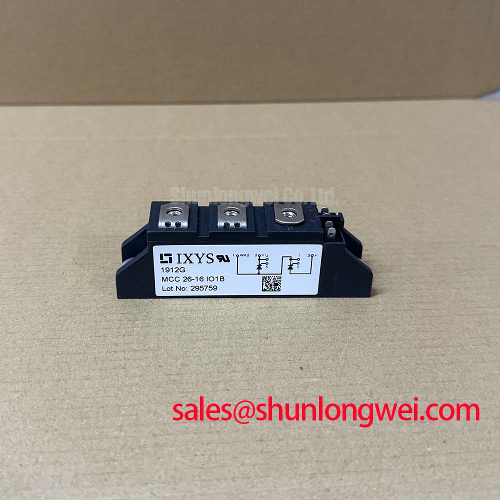
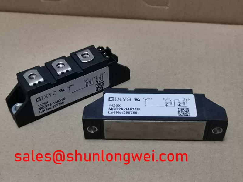
The IXYS MCC26-14IO1B is a dual thyristor module with a 1400 V voltage rating and a 26 A current rating, both Official Specifications supplied for this product. Its stated package is a module. Those ratings establish initial comparison points, not a complete operating limit: the original datasheet and equipment documentation are needed to check how current, temperature and surge conditions apply to the installed circuit.
For a phase-controlled rectifier, first trace each thyristor’s anode, cathode and gate connections against the original schematic. Then check whether the control board delivers firing pulses at the intended points in the AC cycle. A missing or mistimed pulse can alter DC output and device loading without producing an obvious cold-state short. Treat conduction-angle adjustments and their effect on supply harmonics as system-level matters to be verified at the equipment, rather than characteristics established by this module’s voltage and current ratings.
A nearby commutating diode can affect current transfer, but diode reverse-recovery peak current and recovery time are not specified in the supplied MCC26-14IO1B parameters. They must not be assigned to this dual thyristor module. As a Design Consideration, inspect the actual companion diode’s documentation and switching waveforms if commutation loss or radiated noise is suspected. Wolfspeed’s power-module information provides context for other semiconductor technologies, not an interchangeability claim for this IXYS part.
Assembly Integrity and Thermal Interface Contact
Before installing the module, inspect the heatsink seating area for debris, old interface material and uneven contact marks. Apply the thermal interface material according to the equipment or material manufacturer’s instructions, then seat the module without using its terminals to pull the housing into position. This is a Design Consideration intended to reduce contact irregularities; the supplied product data do not establish a baseplate material, a paste thickness or a mounting torque for this model.
Thermal resistance from junction to case, mounting hardware requirements and allowable case temperature require confirmation in the applicable IXYS datasheet. A 26 A rating (Official Specification) alone does not show that an existing heatsink can carry the equipment’s duty cycle. On a repaired assembly, compare case-temperature trends and load current with a known-good operating record where one exists. Unexpected heating warrants checks of contact pressure, terminal condition and firing behavior before attributing it to the semiconductor.
Field alert: Keep power isolated while checking terminal tightness, and use the documented hardware torque rather than tightening until the module housing visibly flexes.
For an alternative-part review, SKKT 106B14E can be placed on the comparison list, but its name is not evidence of a drop-in fit. Verify circuit configuration, terminal map, mounting dimensions, gate requirements and all relevant electrical limits against both original datasheets before approving a replacement.
Gate Firing and Terminal Layout Checks for MCC26-14IO1B
If the rectifier has output but behaves inconsistently under load, inspect the gate drive at the module terminals rather than only at the controller connector. Confirm the measured pulse reaches the intended gate-to-cathode path, and compare pulse timing and shape with the equipment’s service information. Wiring resistance, loose connections or interference can change what reaches a terminal; a meter’s continuity result will not establish correct firing under load.
Gate-pulse rise time, sustaining current and any multi-pulse firing strategy must come from the applicable device and controller documentation. No values for those items are included in the supplied official parameters, so a particular gate-current slew rate cannot be prescribed here. As a Design Consideration, assess the actual pulse waveform under the relevant operating conditions before changing drive components. If the control cabinet also includes an operator display, identify that panel separately; Winstar’s industrial display range is display-technology context, not a source of thyristor gate specifications.
In a rectifier system, a complementary device such as SSIL2890S46C should be assessed by its documented circuit role and ratings rather than by proximity on a parts list. For a proposed green hydrogen electrolyzer DC power rectifier repair, the same rule applies to the MCC26-14IO1B: confirm the installed circuit’s topology, cooling and protective coordination before judging compatibility with that equipment.
Short-Circuit Protection and Fuse Coordination
After a short-circuit event, inspect the fuse and current path before energizing a replacement module. Record the fitted fuse part number, its location relative to the thyristors and the faulted branch shown on the schematic. A fuse that opened confirms an interruption, not that the semiconductor remained within its surge limit. Check the isolated module for abnormal terminal resistance and inspect adjacent conductors and connections for damage.
Fuse coordination requires the manufacturer’s fuse clearing data under the relevant fault conditions and the thyristor’s documented surge and I²t withstand data. Neither an MCC26-14IO1B withstand figure nor a fuse coordination table is present in the supplied specifications. Consequently, no clearing-energy calculation or claim of damage-free protection can be justified from the 1400 V and 26 A ratings alone. The equipment designer should establish the prospective fault current and compare the documented limits before returning the rectifier to service.
As a Design Consideration, keep the power-loop layout compact to limit inductive voltage overshoot during current interruption, then measure the resulting peak voltage in the actual assembly against its documented limits. Check terminal spacing and insulation arrangements against the equipment’s applicable requirements; the module rating by itself does not certify enclosure clearances. For a broader fault-isolation workflow, the Field Engineer’s Handbook can support the sequence of inspection and measurement, while the original device and fuse documents remain controlling for protection limits.