Content last revised on October 13, 2026
MCC95-16IO1B Operational Boundaries: Evaluating Thyristor Reverse Recovery and Surge Limits
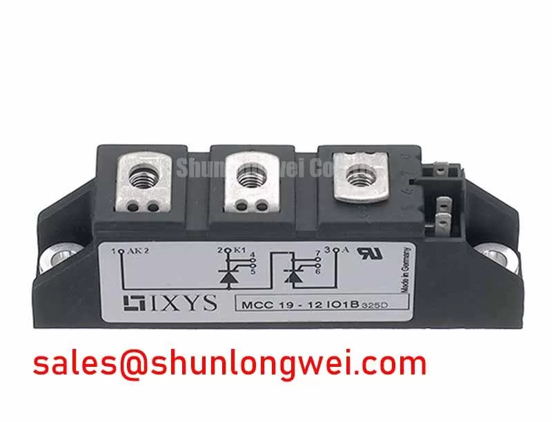
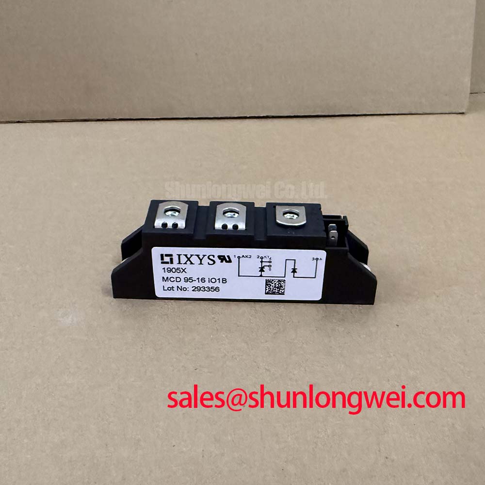
When a high current DC rectifier shows uneven phase current, commutation noise, or repeated fuse operation, isolate the bridge leg before replacing the power module. Confirm terminal identification, inspect the clamping assembly, and compare the gate firing pulse with a known good phase. The IXYS MCC95-16IO1B is a Dual Thyristor Module with a specified blocking voltage rating of 1600 V, a rated average on-state current of 95 A under the manufacturer’s specified conditions, and a Module package designation. Consult the datasheet for the applicable temperature and conduction conditions; the current rating is not an unconditional continuous operating limit.
In a controlled rectifier, reverse recovery behavior influences commutation stress, switching loss, and conducted noise. The service engineer should evaluate the reverse recovery peak current and recovery time against the actual bridge inductance, firing angle, line impedance, and fuse coordination rather than treating the 1600.0 V rating as a complete system limit. Recovery behavior is especially relevant when the module operates beside long bus connections, an interphase transformer, or another rectifier bridge.
Use the manufacturer’s electrical characteristics and fuse I²t coordination data when checking a replacement. The selected semiconductor fuse should coordinate with the module’s permitted surge and fault energy conditions; fuse clearing performance, prospective short circuit current, and repetitive load duty all belong in the same review. A fuse that protects against a catastrophic fault may still permit damaging repetitive commutation stress if the bridge operates near its thermal or surge boundary.
Terminal connections require low resistance and controlled mechanical pressure. Remove oxidation from mating surfaces using the approved service method, keep the conductor path short, and prevent cable force from loading the module terminals. The heatsink interface must remain flat and evenly clamped. Bench Diagnostic: De energize and isolate the rectifier, complete the DC link discharge procedure, and verify absence of hazardous voltage before touching terminals or gate wiring.
For a high current green hydrogen electrolyzer DC power rectifier, engineers should compare line side current sharing, cooling performance, fuse coordination, and the original mechanical footprint before approving a replacement. The module rating is an official component specification, while the usable bridge current remains a system level result established through thermal and electrical verification.
MCC95-16IO1B Operational Boundaries: Evaluating Interphase Transformer Current Balancing Limits
Six pulse and twelve pulse rectifier arrangements distribute current differently through their bridge arms. In a twelve pulse topology, an interphase transformer can support current sharing between parallel rectifier groups, but its leakage characteristics, winding symmetry, saturation behavior, and connection polarity directly affect balance. The MCC95-16IO1B should therefore be assessed as one element within the complete commutation network.
| Item | MCC95-16IO1B | MCC225-16IO1 |
|---|---|---|
| Manufacturer | IXYS | IXYS |
| Category | Dual Thyristor Module | Thyristor Module |
| Blocking voltage rating | 1600 V | Reference the applicable product documentation |
| Rated average on-state current | 95 A under the manufacturer’s specified conditions | Reference the applicable product documentation |
| Package | Module | Reference the applicable product documentation |
The MCC225 16IO1 may be evaluated as a higher current family option when the original mechanical interface, electrical ratings, cooling arrangement, and control circuitry are compatible. It should not be treated as an automatic substitute. Check terminal geometry, isolation requirements, gate characteristics, and the manufacturer’s fuse I²t coordination information before approving any field change.
Current balance can be checked by measuring each bridge group under matched operating conditions and comparing transformer secondary behavior, phase voltage, and thermal rise. A persistent imbalance may involve transformer wiring, firing synchronisation, bus resistance, or magnetic saturation rather than the thyristor module alone. For current feedback and protection circuits, engineers can consult the application resources from ADI High Precision Current Sense Amplifiers and TI Current Sense Amplifiers and Shunt Monitors.
When a rectifier includes a separate front end or parallel conversion stage, the MCD312 18IO1 can be reviewed as a related module within the wider power topology. Compatibility still depends on the circuit function, terminal arrangement, control method, and system ratings.
Transient Dynamics & Electrical Design: Pulse Transformer Isolated Firing Circuit on MCC95-16IO1B
A pulse transformer firing circuit must deliver consistent gate triggering across every line cycle and maintain adequate gate drive until the thyristor anode current exceeds its latching current. Once latched, the thyristor does not require continuous gate drive to remain conducting. The rise rate of gate current, pulse width, back porch gate current, and multi pulse firing strategy should be established from the thyristor gate requirements and the isolated driver design.
Keep the firing loop compact and separate it from high di per dt commutation paths. Minimise parasitic loop inductance to reduce unwanted gate voltage distortion, and verify the actual gate cathode waveform at the module terminals rather than at the driver output. A pulse transformer with excessive leakage, poor reset, or mismatched secondary wiring can produce unequal triggering and localized heating in the bridge.
For turn off transients, the design team should examine thyristor recovery time, reapplied voltage rise rate, and the interaction between commutation inductance and the snubber network. An appropriately rated surge suppression network may be considered when measured overshoot approaches the system insulation or semiconductor margin. The suppression level and available commutation recovery interval must be selected from the complete converter design and validated during controlled tests. This conventional thyristor is not turned off by its gate.
Mechanical assembly also affects transient performance because uneven heatsink pressure can raise junction temperature and alter phase matching. Use the original clamping hardware and manufacturer specified mounting method, then verify flatness, thermal interface coverage, and terminal torque with calibrated tools.
Before energising the complete rectifier, test each isolated firing channel, confirm correct gate cathode polarity, check pulse timing between phases, and review the bridge waveform at reduced operating conditions. Final acceptance should include fuse coordination, current balance, thermal behaviour, and peak voltage margin under the intended electrolyzer DC power duty.