


Content last revised on October 2, 2026
MDC1601634 Circuit Protection and Reliability: Diode Connections, Not Gate Triggering
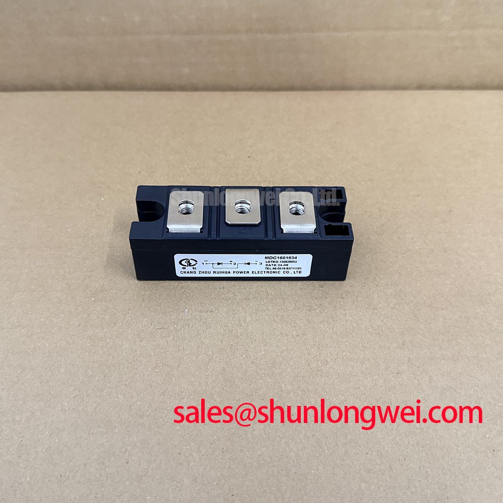
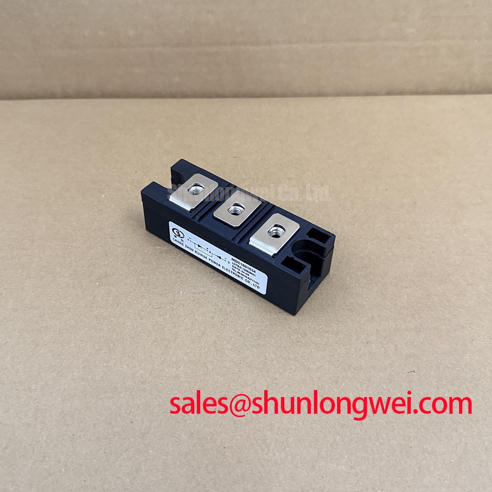
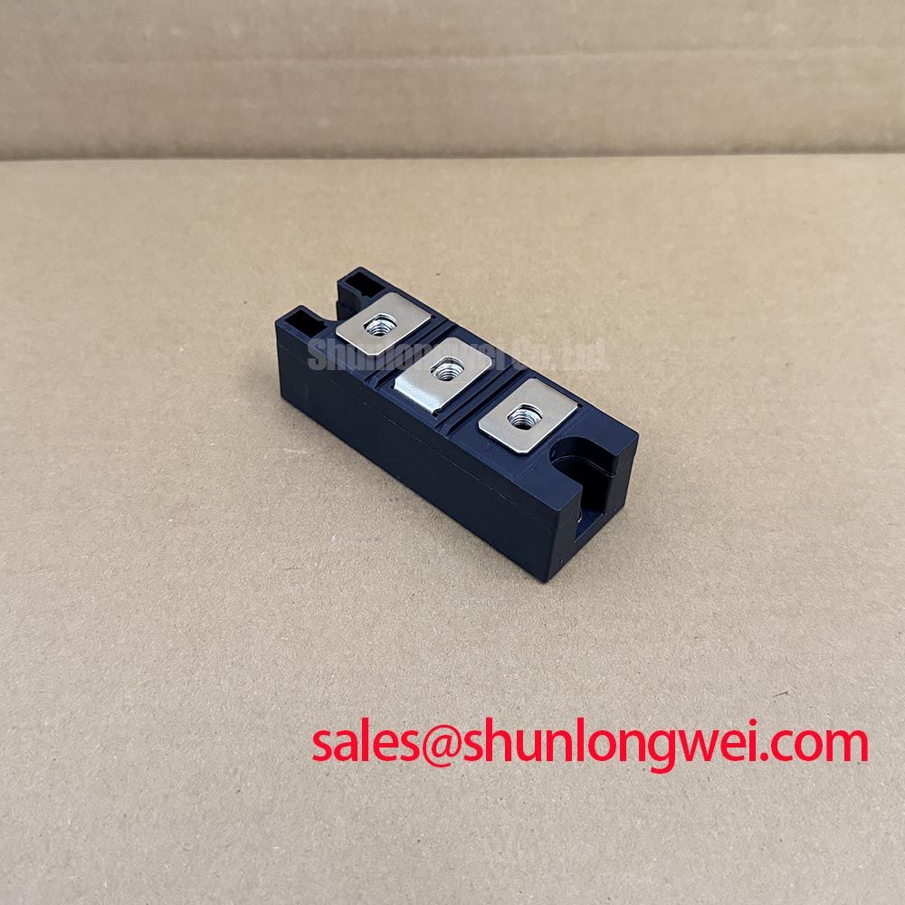
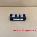
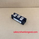
MDC1601634 hardware specification card: Manufacturer: IXYS. Category and topology: Dual Diode Module. Package: SOT-227B / TO-240AA. Series: Standard. These are official product identification and package specifications; no voltage or current rating is supplied in the provided specification data.
Check each diode path with a meter and compare the terminal readings with the equipment schematic before reconnecting the module. The MDC1601634 is a dual diode module, so gate firing pulses, back-porch current and multipulse triggering do not apply to it. A control-board fault involving those signals belongs to a separately identified controlled device, not to either diode in this module.
For protection coordination, trace the actual current path through each diode and its associated fuse. Compare the fuse’s clearing behavior with the module’s surge and thermal limits only when the relevant manufacturer data and circuit fault study are available; the supplied product specifications contain no fuse coordination table or surge-current rating. A measured current waveform is more useful than assuming that the module name encodes an allowable operating current.
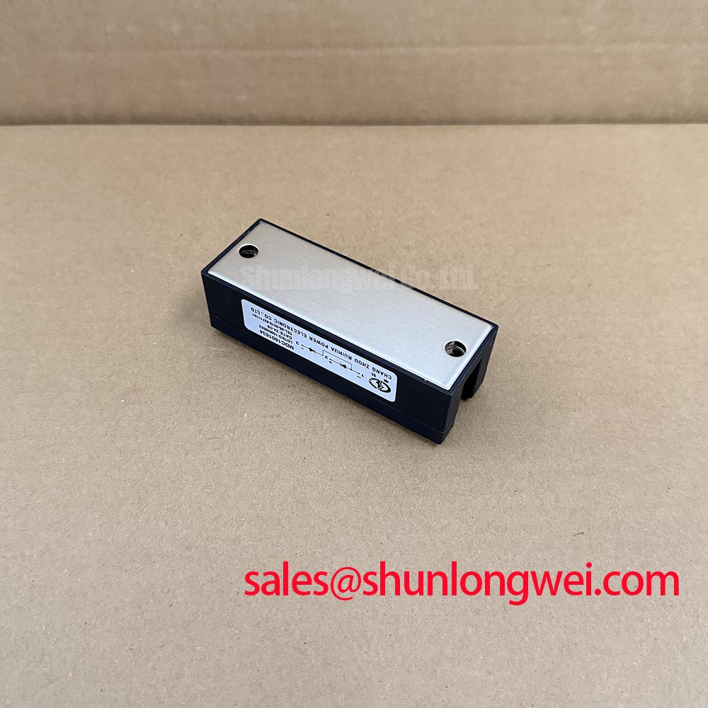
Inspect the heatsink contact surface, terminal hardware and surrounding insulation during service. As a Design Consideration, check terminal tightness against the applicable assembly documentation rather than applying a generic torque to this package. Maintenance note: Isolate the supply before touching the terminals, then inspect for rising contact temperature and restricted heatsink airflow during scheduled maintenance.
Field Diagnostics and Commissioning: Off-State Voltage and Transient Protection
Capture the voltage across the nonconducting diode during commutation and compare it with the corresponding trace from a known-good circuit position. A diode does not undergo gate-induced spurious turn-on: it conducts when its circuit conditions forward-bias it. An unexpected voltage spike instead calls for checks of wiring inductance, snubber condition, switching behavior and the measurement setup.
Where an RC snubber or a metal-oxide varistor is fitted, inspect its connections and measured waveform before changing component values. Snubber resistance and capacitance must be determined from the circuit’s energy, repetition rate and voltage limits, then verified under operating conditions. A series reactor, if present in the original design, also needs evaluation in that circuit rather than being assumed necessary for MDC1601634. These are Design Considerations, not module-specific factory settings.
For a rectifier sharing an enclosure with an industrial drive, compare current-sense readings with an independently observed current waveform when investigating protection trips. The TI current-sense amplifier resources and ADI current-sense amplifier resources describe measurement components; neither establishes a current rating for this diode module.
Field Diagnostics and Commissioning: Reverse Recovery in the Installed Circuit
Probe the commutating diode current and voltage together if turn-off noise or unexpected heating appears during commissioning. Reverse-recovery peak current and recovery time depend on the diode and test conditions, including prior forward current and the rate of current change. No values for these characteristics are present in the supplied MDC1601634 specifications, so assigning a recovery class or calculated switching loss would be unsupported.
Compare waveforms at equivalent operating points and inspect the return path, snubber components and nearby connections if one bridge position behaves differently. A sharp current transition can contribute to voltage overshoot and radiated noise, but the waveform alone does not identify a failed module. When an IGBT commutates the diode elsewhere in the system, The Ultimate IGBT Knowledge Base provides background for examining the switching path; the diode’s measured limits and the system test results still govern the assessment.
During planned maintenance, clear dust from the heatsink and examine the thermal interface for disturbance or deterioration. Record temperature trends under comparable load and ambient conditions so that a change can be investigated without attributing it automatically to reverse recovery.
MDC1601634 Operational Boundaries: Multi-Bridge Rectifier Evaluation
Trace each diode position on the bridge drawing and verify terminal orientation before evaluating MDC1601634 in a multi-bridge assembly. In a six-pulse or twelve-pulse rectifier, module suitability depends on the verified terminal arrangement, blocking-voltage rating, current rating, surge capability and thermal data. The supplied product specifications confirm the dual diode topology and SOT-227B / TO-240AA package, but provide none of those electrical ratings. Package fit alone therefore cannot establish interchangeability.
For a potential high-current green hydrogen electrolyzer DC power rectifier, designers should measure current sharing and temperatures across bridge positions at representative operating points. If an interphase transformer is present, its connection and current balance are system-level checks. A comparison with RM150UZ-2H requires documented electrical ratings, terminal mapping and mounting details for both parts; it is not a drop-in substitution claim. Likewise, DD200KB160 can be examined as a separate topology reference without assuming that it performs the same circuit role.
At the next service interval, inspect for condensation and corrosion around terminals, confirm that cooling passages remain clear, and compare contact temperatures with previous readings taken under similar load. Escalate any unexplained imbalance to a review of the bridge schematic, connection condition and measured waveforms before changing components.