

Content last revised on September 11, 2026
Transient Dynamics & Electrical Design: Interphase Transformer Current Balancing on DD200KB160
| Specification | Official Value |
|---|---|
| Manufacturer | SanRex |
| Product category | Diode Module |
| Repetitive peak reverse voltage | 1600 V VRRM |
| Average forward current per arm | 200 A at Tc = 94°C |
| Surge forward current at 60 Hz | 6000 A IFSM |
| Forward voltage drop at 600 A | 1.35 V VFM |
| Isolation voltage, AC for 1 minute | 2500 V Visol |
| Junction temperature range | −40°C to +150°C |
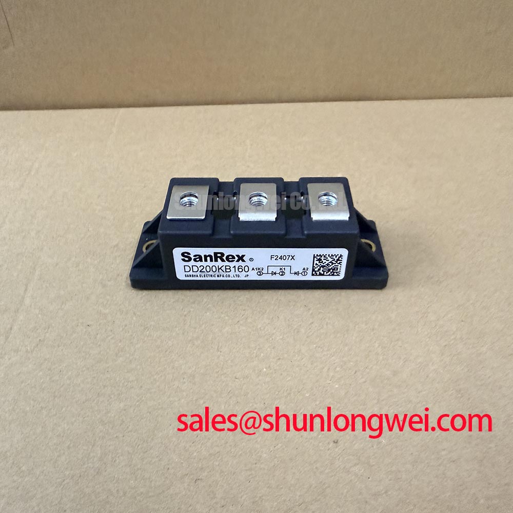
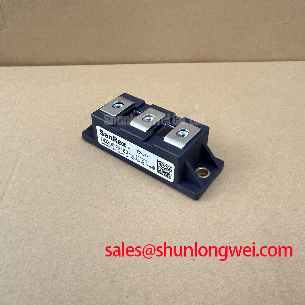
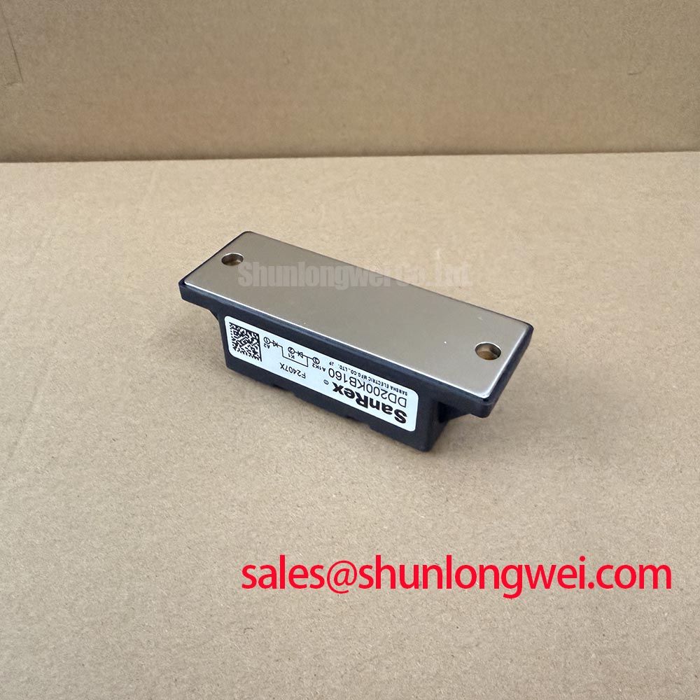
Measure the current in each rectifier arm with a calibrated current probe while the converter is operating, then compare the waveform symmetry around the interphase transformer. The DD200KB160 is specified for a repetitive peak reverse voltage of 1600 V and an average forward current per arm of 200 A at Tc = 94°C. These values define the device rating boundary; they do not by themselves establish the allowable current of a complete six pulse or twelve pulse bridge.
In a six pulse arrangement, inspect each conducting path for unequal current, abnormal commutation notches, and excessive reverse voltage. In a twelve pulse system, verify the phase displacement and the interphase transformer connection against the equipment schematic. Unequal secondary voltage, transformer leakage differences, terminal resistance, or an incorrectly connected balancing network can shift current into one arm. The replacement inspection should therefore include terminal identification, cable condition, busbar flatness, and the torque procedure specified by the original assembly documentation.
Coordinate the semiconductor fuse with the fuse manufacturer’s published I²t curve and the module’s actual application waveform. The supplied product data confirms a 6000 A IFSM at 60 Hz, but this surge rating is not a substitute for a fuse coordination table or a short circuit withstand guarantee. During commissioning, capture the line-to-line voltage, bridge current, and reverse voltage at the module terminals. Engineers evaluating high-current green hydrogen electrolyzer DC power rectifiers can also review the neutral DDB6U144N10R product data when comparing bridge topology requirements.
Benchtop Waveform Tuning: Mitigating Stress via High-di/dt Commutation: Pulse-Train Timing on DD200KB160
Trace the firing signal and the corresponding anode-to-cathode voltage at the device terminals before changing the trigger circuit; a diode module does not provide a gate-control interface, so gate pulse specifications cannot be assigned to this model. The electrical review should instead concentrate on commutation overlap, reverse recovery behavior in the complete bridge, and the wiring inductance between the transformer, rectifier, and DC link.
When a controlled rectifier shares a power cabinet with switching stages, inspect the control harness for coupling from high-current conductors. A pulse train intended for a separate thyristor or IGBT stage must not be treated as a control input for the DD200KB160. Use an oscilloscope with suitable differential and current probes to compare the known-good phase path with the suspect path. Sudden reverse-voltage overshoot, ringing, or current imbalance should lead to checks of snubber condition, commutation inductance, transformer phase sequence, and the physical terminal joints.
The specified forward voltage drop is 1.35 V at 600 A. Use that factory value as a reference point for power-loss estimation, while recognizing that actual loss varies with current waveform, temperature, and operating conditions. The manufacturer’s electrical data should remain the source for any recovery or switching limits required by the final design. General power-semiconductor measurement practices can be cross-checked against information from SanRex Sansha Electric Power Semiconductor Modules, an industry reference for power semiconductor modules.
Preventing Spurious Faults: Phase-Controlled Rectification, Firing Angle Guidelines for DD200KB160
Record the firing reference, phase voltage, DC output, and bridge current simultaneously when a phase-controlled rectifier reports intermittent faults. The DD200KB160 is a diode module, so firing-angle control belongs to the upstream controlled devices or converter controller rather than to this module itself. Its role must be confirmed from the circuit drawing before diagnosing a firing sequence.
For a six pulse or twelve pulse power supply, compare the measured DC waveform with the expected bridge topology and transformer phase relationship. At advanced or delayed firing conditions, power factor and reactive power can change at system level; these effects should be evaluated from measured line current and the converter’s control scheme, not inferred from the diode’s voltage rating. Check whether a faulty controlled arm, a disturbed synchronization signal, or an interphase transformer connection is forcing abnormal reverse voltage onto the diode path.
The 2500 V AC isolation voltage for one minute is an official specification for the module’s isolation test condition. It should not be presented as a complete cabinet insulation or system safety certification. In a rectifier cabinet, keep the intended creepage, clearance, grounding, and protective coordination under system engineering control. A front-end or auxiliary rectification stage may be reviewed alongside DDB6U100N14R where the equipment topology requires a separate complementary device.
Assembly Integrity & Layout Architecture: Implementing Junction-to-Heatsink Heat Dissipation
Check the heatsink contact pattern, baseplate seating, and temperature rise across the mounting area when the rectifier shows thermal imbalance. The DD200KB160 has an official junction temperature range of −40°C to +150°C, while the stated current rating is tied to Tc = 94°C; therefore, enclosure airflow, heatsink condition, and contact quality directly affect the usable operating point.
Remove oxidation and contamination from mating surfaces using the approved maintenance method, inspect the thermal interface material for drying or pump-out, and apply the assembly procedure specified for the original heatsink and fasteners. Do not infer a model-specific mounting torque when it is absent from the supplied factory data. Tighten progressively and evenly to avoid baseplate distortion, then verify that power terminals remain mechanically supported without transferring cable load into the module body.
Measure temperatures at comparable positions on each bridge arm during a controlled load test. A rising difference between arms may indicate unequal current sharing, degraded thermal contact, restricted airflow, or a loose connection, so confirm the cause with electrical and mechanical measurements rather than a single temperature reading. Maintenance Note: keep the heatsink and air path clean, and periodically check contact temperature and terminal tightness after thermal cycling.
For higher-power maintenance planning, the practical thermal interface and cooling principles discussed in The Advanced Thermal Management Revolution provide a useful reference when assessing heatsink contact and system-level cooling architecture.