Content last revised on September 20, 2026
Preventing Spurious Faults: Reverse Recovery Charge Temperature Coefficients for SKD30/08A1
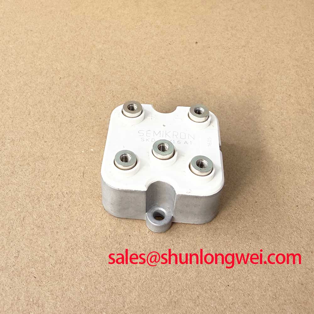
The stated factory electrical boundary for the SKD30/08A1 is 800 V and 30 A. These values are Official Specification data supplied for this product identification. They establish the initial rating check, but they do not provide a published reverse-recovery current, reverse-recovery time, recovery charge, junction-to-case thermal resistance, surge current, or fuse coordination value in the available product data. Those values must not be inferred from the Semipont housing or from the model designation.
In a rectifier assembly, commutation-related noise can arise from the combined behavior of the transformer, wiring, capacitors, busbars, snubber network, protective devices, and the rectifier module. A disturbance that appears after a replacement may indicate an issue in any of those connected elements. The practical check is to compare voltage and current waveforms at the module terminals with the original control sequence and with a known-good channel where one exists. Engineers should use suitably rated differential voltage and current measurement equipment and verify the measurement reference arrangement before interpreting high-energy switching waveforms.
Reverse recovery characteristics vary with current, temperature, commutation rate, source inductance, and the actual semiconductor construction. Since no official values for peak reverse-recovery current or recovery interval are provided here, it is not appropriate to assign the SKD30/08A1 a soft-recovery classification or predict its electromagnetic behavior. A Design Consideration is to keep the commutation loop physically compact where the equipment layout permits, because loop inductance can contribute to voltage excursion and radiated disturbance during current transfer. Final acceptability belongs to system-level switching tests rather than a housing-level assumption.
For medium-frequency induction melting and hardening furnace power supplies, a rectifier stage may be evaluated as part of the upstream DC source feeding the subsequent power conversion section. This is an application example only, not a statement that the module is dedicated to that equipment. When a furnace supply develops nuisance overvoltage trips, unstable DC bus behavior, or repeated protective fuse operation, check transformer secondary connections, busbar contact condition, suppression components, capacitor health, and trigger timing in the wider converter before assigning the event to diode recovery behavior.
Metal-oxide varistors can be used in some equipment as part of an overvoltage suppression arrangement, but their selection and placement are system-determined. A Design Consideration is to verify their energy handling, clamping behavior, isolation arrangement, and interaction with the existing fuse and capacitor network against the measured transient at the installed DC-link voltage. The module’s stated 800 V rating should remain the fixed reference for this verification. No MOV clamp level or absorbed-energy value should be selected from the module rating alone.
Terminal connections deserve the same scrutiny as waveform behavior. Oxidation, uneven contact faces, incorrect conductor stacking, and hardware that has loosened under thermal cycling can all increase local resistance. That can produce heat and voltage disturbance that resemble a semiconductor fault. Clean only by procedures compatible with the equipment service manual, use the intended conductor orientation, and verify that each terminal is electrically isolated from adjacent conductors as required by the original assembly.
Semikron-Danfoss maintains an official power electronics and modules hub that can assist engineers in locating manufacturer-level product-family context. Product-family material is useful for terminology, but the replacement decision should remain tied to the exact SKD30/08A1 marking, the declared 800 V and 30 A ratings, the Semipont housing, and the original equipment connection arrangement.
Transient Dynamics & Electrical Design: Short-Circuit Withstand Limits Coordination for SKD30/08A1
A dead-short event is a protection-coordination problem involving the entire energy path. The available official data identifies the SKD30/08A1 as a Semikron Semipont bridge rectifier module with an 800 V voltage rating and 30 A current rating. It does not state a semiconductor-fuse I²t capability, a non-repetitive surge-current value, a permissible short-circuit duration, or a clearing-energy limit. It would therefore be unsafe to calculate a fuse match or claim zero-damage performance from the published identification data alone.
The correct service procedure is to obtain the original equipment protection schedule and compare the fuse manufacturer’s time-current and I²t documentation with the specific module datasheet and the measured prospective fault condition. The system engineer must include transformer impedance, bus inductance, stored capacitor energy, conductor path, and the actual point of failure in that assessment. A fuse selected for one rectifier arrangement cannot be assumed suitable for another simply because the modules share a similar package family.
When a semiconductor fuse has operated, inspect the broader circuit before fitting a replacement module. Check for a downstream busbar short, damaged capacitor bank, transformer fault, incorrectly sequenced contactor, suppressed transient path, or conduction path created by wiring damage. A fuse operation may be evidence of an excessive current event, but it does not identify the initiating location without supporting measurements. Conduct insulation and continuity checks only with test conditions approved by the equipment manufacturer and suitable for connected electronic controls.
Parallel paths also require care. Current sharing in parallel semiconductor paths depends on actual static voltage characteristics, conductor resistance, thermal coupling, commutation behavior, and symmetry of the complete layout. A Design Consideration is to compare all branch connections and thermal interfaces rather than assuming that the positive temperature coefficient of a separate device type will guarantee equal sharing in this bridge rectifier module. No official parallel-operation rating or dynamic sharing specification is provided for the SKD30/08A1 in the supplied data.
Where an existing installation uses a comparable Semikron-family reference such as SKD82/18, the part number must not be treated as proof of substitution compatibility. Voltage class, current rating, internal circuit arrangement, terminal layout, fuse coordination, cooling arrangement, and original control requirements must each be checked. A higher or differently coded part number does not establish electrical interchangeability.
For service teams evaluating fault protection around a rectifier input, the Power Electronics Masterclass offers a useful reference point for organizing bus voltage, current path, switching transient, and thermal verification. It should be used as a testing framework, while the final fault-protection decision remains dependent on the exact module documentation and the installed converter’s validated protection design.
SKD30/08A1 Operational Boundaries: Evaluating Phase-Controlled Rectification, Firing Angle Limits
The SKD30/08A1 is identified as a bridge rectifier module, so the first operational question is whether the installed equipment uses an uncontrolled bridge arrangement or a phase-controlled topology using separate controlled devices. The supplied product data does not define gate terminals, gate-trigger characteristics, firing angle capability, controlled rectifier topology, or phase-control limits for this model. Engineers should not apply firing-angle calculations to the SKD30/08A1 unless the original circuit drawing explicitly establishes how this module participates in the converter.
In a phase-controlled rectification system, firing angle changes alter the energy transferred from the AC source to the DC output. As the firing point is delayed, the source current waveform and reactive-power demand can change substantially. Those are system-level properties influenced by transformer design, load inductance, commutation overlap, line impedance, control timing, and filtering. No statement about allowable firing range, power factor, or reactive-power performance can be attributed to this bridge rectifier module without manufacturer documentation for the complete controlled assembly.
For medium-frequency induction heating equipment, technicians often encounter a rectifier stage upstream of a DC-link capacitor bank and inverter section. If the furnace fails to establish or hold process power, separate the AC input, rectifier output, DC link, and inverter sections during diagnosis. Confirm that the measured AC source is present under the intended operating condition, inspect the rectifier output path for unwanted continuity, and compare control signals with the original schematic. A low DC output may arise from input supply conditions, contactor issues, transformer connections, control sequencing, damaged capacitors, or downstream loading as well as module-related concerns.
The 800 V official voltage rating must be compared directly with the highest voltage the installed bridge can experience, including normal operating variation and measured switching excursions. The 30 A official current rating likewise needs to be assessed against the application’s actual current waveform, duty condition, cooling state, and protective arrangement. Rating labels are not a substitute for waveform verification where pulsed or non-sinusoidal current is present.
Do not confuse a bridge module with a gate-driven semiconductor stage simply because both appear in the same furnace cabinet. Gate-drive bootstrap capacitors, driver-diode recovery, dead time, and firing logic belong to the relevant controlled switching stage. They are not confirmed characteristics of the SKD30/08A1 from the supplied product information. During a repair, trace the physical conductor and schematic node from the bridge output to the DC link before deciding which control or protection subsystem requires attention.
SKD30/08A1 Thermal-Electrical Optimization: Thermal Interface Material Spreading Across Practical Tuning
Inspect the mounting face and heatsink before installation of the SKD30/08A1 Semipont module. The goal is consistent physical contact across the intended mounting area, without debris, burrs, old hardened compound, or mechanical distortion that prevents the surfaces from seating correctly. The supplied official data does not state the module’s junction-to-case thermal resistance, mounting-hole hardware, tightening sequence, mounting torque, baseplate construction, or thermal-interface material thickness. These details must be taken from the applicable Semikron documentation and the original equipment service specification.
Thermal compound is intended to fill microscopic surface irregularities rather than create a thick insulating layer. A Design Consideration is to apply it evenly and sparingly according to the approved maintenance procedure, then verify that the module sits flat before final tightening. Excess material can contaminate surrounding connections, while insufficient coverage can leave contact areas poorly coupled to the heatsink. Neither condition can be judged reliably by electrical ratings alone.
Use the original tightening sequence and torque requirement for the specific Semipont installation. Torque values often depend on the exact mounting hardware and heatsink construction, so a general industry value must not be presented as an official SKD30/08A1 requirement. Where the original document is unavailable, the responsible system engineer should obtain the mechanical specification before returning high-current equipment to service. Uneven clamping force can alter thermal contact and may also place unnecessary stress on the module housing.
After mechanical installation, verify terminal alignment before connecting power conductors. Conductors should enter without forcing the module terminals sideways or twisting the housing. Recheck the clearance to adjacent live parts, the intended insulation barriers, and the condition of any busbar support. The module’s declared 800 V rating is an electrical rating, not a substitute for equipment-level insulation coordination, clearance, creepage, enclosure protection, or safety certification.
A controlled commissioning sequence is more informative than a single high-load restart. With the system’s approved safety procedures in place, technicians can monitor expected input, rectifier output, heat-sink behavior, protective-device response, and abnormal vibration or connection heating. If observations differ from the known operating pattern, remove power and return to circuit-level checks. Avoid assigning a specific thermal resistance or junction-temperature margin where those official SKD30/08A1 parameters have not been provided.